Ducted power plant and aircraft

A technology of a power unit and a drive unit, applied in the field of aircraft, can solve the problems of shortened life, slow response speed of speed increase, complicated control system, etc., and achieve the effects of extending service life, speeding up the device quickly, and shortening the response time.

Active Publication Date: 2017-10-17
ZHUHAI PANSHI ELECTRONICS TECH CO LTD
View PDF2 Cites 0 Cited by
  • Summary
  • Abstract
  • Description
  • Claims
  • Application Information

AI Technical Summary

Problems solved by technology

[0005] 1. The speed-up response speed is slow, and it is impossible to achieve fast speed-up and obtain large power;
[0006] 2. Only by increasing the speed to increase the power, the speed reaches the limit, the power cannot continue to increase, and the range of power increase is not large;
[0007] 3. When frequent and large acceleration and deceleration are required, the power of the motor needs to be adjusted accordingly, which will easily cause motor loss and shorten its life
But this kind of structure is complex, takes up a lot of space, and the control system is complex and costly

Method used


Image

  • Ducted power plant and aircraft
  • Ducted power plant and aircraft
  • Ducted power plant and aircraft

Examples


Embodiment Construction

[0045] Example of Ducted Power Plant

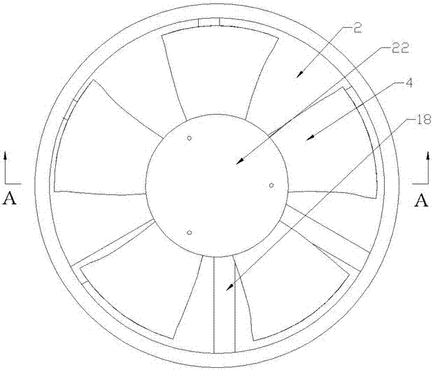
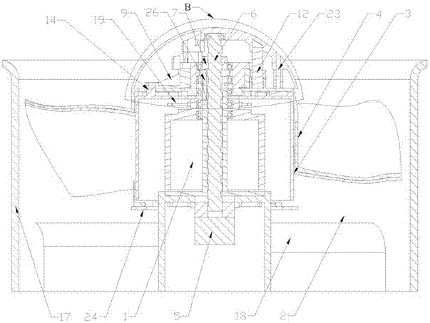
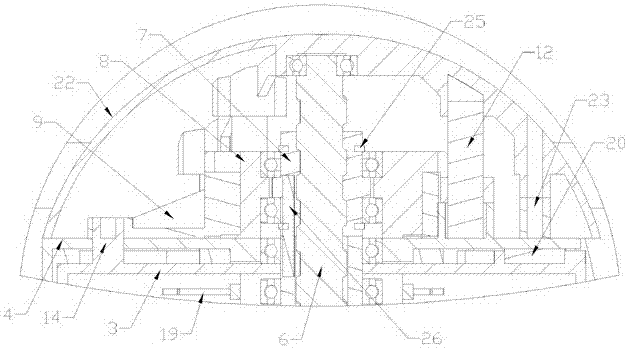
[0046] Such as figure 1 with Figure 12 As shown, the present invention includes a duct 2, a driving device 1, a first rotor 3, a second rotor 4, a top cover 22, a second rotating member 8 and a first rotating member 9 connected to a threaded bush 7 through a bearing. In the present invention, the driving device 1 is a motor 1 . Such as figure 2 As shown, the duct 2, the first rotor 3 and the second rotor 4 are coaxially arranged. The second rotor 4 can rotate relative to the first rotor 3 around the co-axis through a separation mechanism. Wherein the first rotor 3 and the second rotor 4 belong to the rotor of the whole power plant. Such as Figure 9 As shown, a connecting ring 24 is installed on the bottom of the second rotor 4, and the connecting ring 24 is used to prevent the rotor from vibrating in the axial direction, so as to prevent the two rotors from colliding with each other and being damaged due to vibration. Motor 1 is...


PUM


Abstract

The invention relates to a duct power device and an aircraft. The duct power device comprises a driving device, a duct and rotor wings, wherein the duct and the rotor wings are arranged coaxially; the rotor wings comprise a first rotor wing and a second rotor wing which are coaxially arranged and can rotate around a coaxial line, the second rotor wing rotates relative to the first rotor wing around the coaxial line through a separating mechanism. When output power needs to be promoted, propeller blades on the second rotor wing are separated from propeller blades on the first rotor wing, and the number of the propeller blades in the duct is doubled; with the increase of the number of the propeller blades, large power can be obtained in a short time, so that the purposes of shorting corresponding time and quickly increasing the speed of the device are achieved, and the power limit of the duct power device is also effectively promoted. In addition, the service life of the driving device is indirectly prolonged. The aircraft disclosed by the invention comprises the duct power device, wherein the duct power device is arranged on the aircraft frame of the aircraft.

Description

technical field [0001] The invention relates to the field of aircraft, in particular to a power device with a duct and an aircraft using the duct power device. Background technique [0002] The ducted power unit equipped on the aircraft generally includes ducts, rotors and motors coaxially arranged in the ducts, and the motors can also be arranged on the periphery of the ducts and drive the rotors to rotate through the drive shaft device to achieve normal work in the ducts. [0003] In the prior art, the ducted power device usually achieves the purpose of increasing the rotation speed of the rotor and thus the flight speed by increasing the power of the motor. For example, the Chinese patent application whose publication number is CN 104401480 A discloses a ducted tilting aircraft. It is recorded in this patent application that the aircraft includes a fuselage, and a duct is provided on the fuselage, and a ducted propeller is installed in the duct. This solution increases ...

Claims


Application Information

Patent Timeline
Patent Type & Authority Patents(China)
IPC IPC(8): B64C11/20B64C27/10
CPCB64C11/20B64C27/10
Inventor 何春旺
Owner ZHUHAI PANSHI ELECTRONICS TECH CO LTD
Why Eureka
Try Eureka