A high power polarized laser device

A laser device and high-power technology, applied in lasers, laser parts, phonon exciters, etc., can solve the problems of inability to achieve high-power polarized laser output, serious thermal effects, and difficulty in specific wavelength output, and achieve high-power Polarized laser output, excellent thermodynamic and mechanical properties, improved electro-optical efficiency

Active Publication Date: 2022-06-21
TECHNICAL INST OF PHYSICS & CHEMISTRY - CHINESE ACAD OF SCI +1
View PDF0 Cites 0 Cited by
  • Summary
  • Abstract
  • Description
  • Claims
  • Application Information

AI Technical Summary

Problems solved by technology

However, due to the large quantum deficit of Tm:YAG laser, serious thermal effect, rich gain spectrum, and many laser channels, it is difficult to output specific wavelengths, and it is impossible to achieve high-power polarized laser output. There is no way to achieve polarized laser output by pumping Tm:YAG crystals. technical solutions

Method used


Image

  • A high power polarized laser device
  • A high power polarized laser device
  • A high power polarized laser device

Examples


no. 1 example

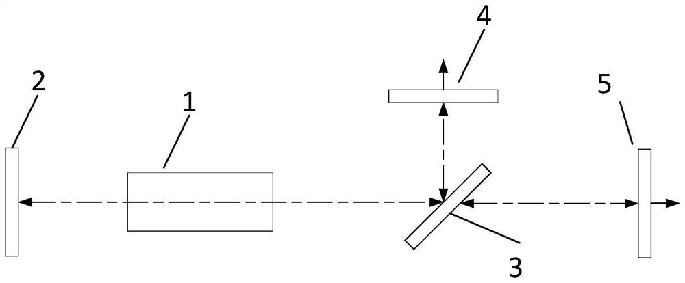
[0028] Based on the above findings, the present invention provides a high-power polarized laser device, including a high-reflection mirror 2, a laser gain module 1, a polarizer 3, an s-light output mirror 4 and a p-light output mirror 5, wherein the high-reflection mirror 2, the laser gain The module 1 and the polarizer 3 are placed on the same optical axis in sequence, the s light output mirror 4 is located on the reflected light path of the polarizer 3 and is perpendicular to the transmission direction of the reflected light, and the p light output mirror 5 is located on the polarizer 3 to transmit. The light path is perpendicular to the transmission direction of the transmitted light. The s-light output mirror 4 reflects part of the s-polarized laser on the reflected light path of the polarizer 3 back to the original path, forms a resonant cavity with the high-reflecting mirror 2, and partially emits to form a polarized laser, and the p-light output mirror 5 will Part of th...

no. 2 example

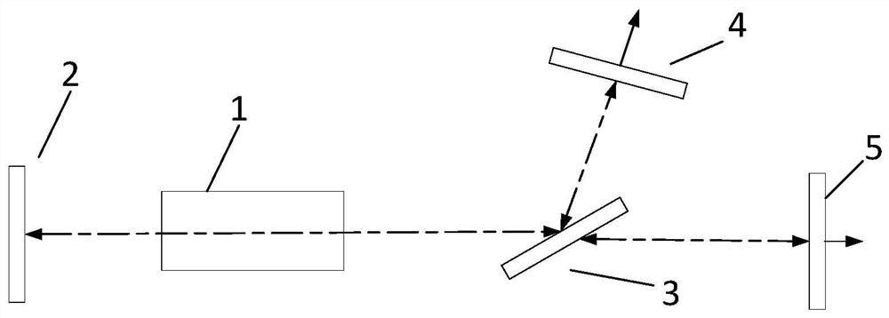
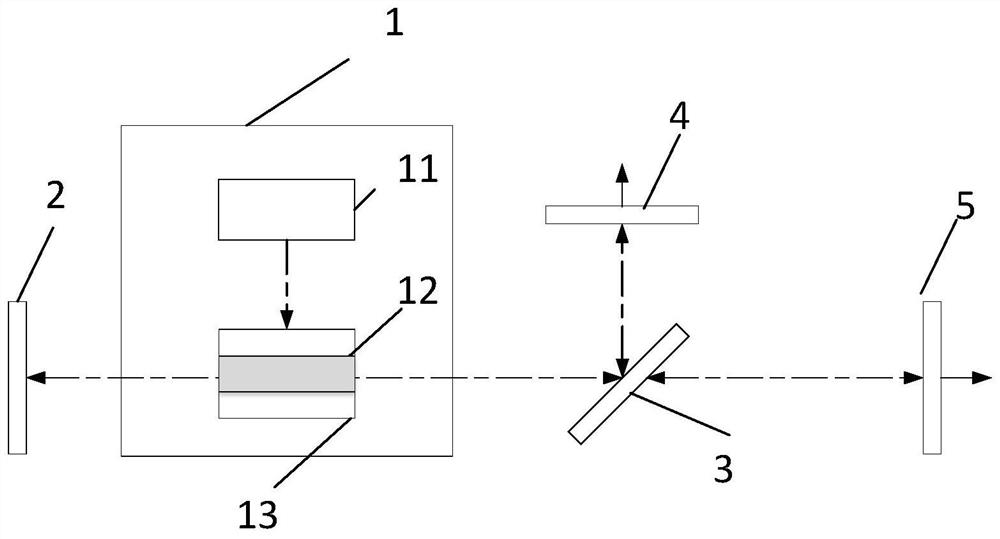
[0034] Another embodiment of the high-power polarized laser device of the present invention is as follows: image 3 As shown, it includes a high-reflection mirror 2, a laser gain module 1, a polarizer 3, an s-light output mirror 4 and a p-light output mirror 5, wherein the high-reflection mirror 2, the polarizer 3, the s-light output mirror 4 and the p-light output mirror The structure of the light output mirror 5 is the same as that of the previous embodiment, and will not be repeated here. The laser gain module 1 further includes a pump source 11 , a laser gain medium 12 and a heat sink 13 , wherein the pump source 11 is a side pump. The side pump source is a laser diode (Laser Diode), which is located on the side of the laser gain medium 12 and is used to pump the laser gain medium 12. In this embodiment, the wavelength of the side pump source is 780 nm. Wavelength, the 780nm waveband refers to the waveband of 780nm to 790nm. Preferably, a laser diode with a wavelength of 7...

no. 3 example

[0038] In order to increase the power of the polarized laser device and reduce the thermal effect, the high-power polarized laser device of the present invention can also be as follows: Figure 5 As shown, the difference from the previous embodiment is that the high-power polarized laser device includes at least two laser gain modules 1, and the laser gain modules 1 are connected in series. For the convenience of description, the embodiment of the present invention uses two laser gain modules. Module 1 is taken as an example for description. The structure of the laser gain module 1 is the same as that of the laser gain module using the side-pump pump source in the previous embodiment. In this implementation, the laser gain module pumps a Tm:YAG crystal through a 785nm pump source, and achieves a mid-range 2μm band. Laser output at a specific wavelength.


PUM

PropertyMeasurementUnit
reflectanceaaaaaaaaaa

Abstract

The invention provides a high-power polarized laser device, which comprises a high reflection mirror (2), a laser gain module (1), a polarizer (3) placed in sequence, and placed on the optical path of the s-polarized laser light reflected by the polarizer (3). The s light output mirror (4) and the p light output mirror (5) placed on the optical path of the polarizer (3) transmitted light p-polarized laser light, the s light output mirror (4) makes the s-polarized laser light reflect vertically Returning according to the original optical path forms resonance with the high reflection mirror (2), and the p-light output mirror (5) makes the vertical reflection of the p-polarized laser light return according to the original optical path to form resonance with the high reflection mirror (2). The device uses Tm:YAG crystal as the laser gain medium, and realizes high-power polarized laser output by precisely matching the gain and loss relationship between p-polarized laser and s-polarized laser. It is an efficient, compact and highly reliable 2μm band polarized laser. new technology approach.

Description

technical field [0001] The invention relates to a high-power solid-state laser, in particular to a high-power polarized laser device. Background technique [0002] Due to its unique superior characteristics, the ~2μm coherent radiation source has shown better performance in the fields of laser ranging, laser remote sensing, laser imaging, medical diagnosis and treatment, scientific research, material processing, optical signal processing, data processing, and environmental monitoring. Wider application prospects. [0003] At present, the technical solution for generating ~2μm laser light through a direct laser process is mainly to use a semiconductor laser to pump thulium-doped (Tm 3+ ), holmium (Ho 3+ ) and other rare-earth ions in the laser gain medium to directly generate a 2μm all-solid-state laser. At present, the realization methods of all-solid-state 2μm lasers mainly focus on the following: (1) About 790nm semiconductor laser pumped single-doped Tm 3+ Laser cryst...

Claims


Application Information

Patent Timeline
Patent Type & Authority Patents(China)
IPC IPC(8): H01S3/0941H01S3/08H01S3/16H01S3/042
CPCH01S3/0941H01S3/08054H01S3/1616H01S3/1643H01S3/042
Inventor 宗楠申玉彭钦军薄勇杜仕峰
Owner TECHNICAL INST OF PHYSICS & CHEMISTRY - CHINESE ACAD OF SCI
Why Eureka
Try Eureka