
Dynamic coordination control method and device for AVC and SVG of new energy pooling station

A technology of dynamic coordination and control method, applied in the direction of circuit device, system integration technology, reactive power adjustment/elimination/compensation, etc., can solve the problem of reducing multiple reactive power, system voltage drop, and difficulty in fully utilizing SVG dynamic reactive power response capability and other issues to achieve the effect of improving efficiency and increasing power limit

Pending Publication Date: 2022-04-22
NORTH CHINA ELECTRICAL POWER RES INST +2
View PDF0 Cites 0 Cited by
  • Summary
  • Abstract
  • Description
  • Claims
  • Application Information

AI Technical Summary

Problems solved by technology

However, limited by the communication speed of the AVC system and the power flow calculation speed of the large power grid, the AVC master station usually sends instructions to the AVC sub-station every 5 minutes, and the AVC sub-station usually sends instructions to the SVG in seconds, which greatly affects the Limits the millisecond-level control responsiveness of SVG
At the same time, the SVG operates in the constant reactive power control mode, so it is only suitable for the steady state operation of the system, and cannot respond to the transient process of the system, making it difficult to fully utilize the dynamic reactive power response capability of the SVG
When a large disturbance occurs in the system, SVG continues to maintain the AVC reactive power distribution control command, and cannot respond to the system voltage drop in time to generate reactive power, and may even be in a state of absorbing reactive power, resulting in a further drop in system voltage

Method used


Image

  • Dynamic coordination control method and device for AVC and SVG of new energy pooling station
  • Dynamic coordination control method and device for AVC and SVG of new energy pooling station
  • Dynamic coordination control method and device for AVC and SVG of new energy pooling station

Examples


Embodiment Construction

[0060] In order to make the purpose, technical solutions and advantages of the embodiments of the present application clearer, the technical solutions in the embodiments of the present application will be clearly and completely described below in conjunction with the drawings in the embodiments of the present application. Obviously, the described embodiments It is a part of the embodiments of this application, not all of them. Based on the embodiments in this application, all other embodiments obtained by persons of ordinary skill in the art without creative efforts fall within the protection scope of this application.

[0061] Considering the communication speed of the AVC system and the power flow calculation speed of the large power grid, the AVC master station usually sends instructions to the AVC sub-station every 5 minutes, and the AVC sub-station usually sends instructions to the SVG in seconds, which greatly limits the SVG Millisecond-level control responsiveness. At ...


PUM


Abstract

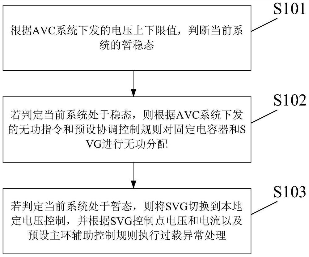
The embodiment of the invention provides a new energy pooling station AVC and SVG dynamic coordination control method and device, and is applied to an SVG master control unit connected between an AVC system and a fixed capacitor in a new energy pooling station, and the method comprises the steps: judging the transient and steady state of a current system according to the upper and lower limit values of the voltage issued by the AVC system; if it is judged that the current system is in a steady state, reactive power distribution is carried out on the fixed capacitor and the SVG according to a reactive power instruction issued by the AVC system and a preset coordination control rule; if the current system is judged to be in the transient state, switching the SVG to local constant voltage control, and executing overload exception processing according to the SVG control point voltage and current and a preset main ring auxiliary control rule; according to the invention, the power limit of the new energy collection area can be effectively improved.

Description

technical field [0001] This application relates to the field of energy management, in particular to a method and device for dynamic coordinated control of AVC and SVG in a new energy gathering station. Background technique [0002] Due to the strong volatility of new energy, it is difficult to balance the reactive power and voltage, and the new energy power generation equipment provides little or no reactive power, the voltage of the access point is often low, which greatly restricts the ability to send new energy. Therefore, reactive power compensation equipment is widely used in new energy sources and plays an important role in reactive power and voltage balance. [0003] Generally speaking, new energy collection stations are equipped with fixed-capacity reactive power compensation equipment, such as capacitors and continuously adjustable reactive power compensation equipment static var generator (SVG). Fixed capacitors are low in cost, but due to the limited application ...

Claims


Application Information

Patent Timeline
Patent Type & Authority Applications(China)
IPC IPC(8): H02J3/18H02J3/38H02J3/46H02J13/00
CPCH02J3/18H02J3/38H02J3/46H02J3/466H02J13/00032Y02E40/10Y02E40/70Y04S10/12Y04S10/22Y04S10/50
Inventor 卢文清李长宇谢欢吴涛梁倍华赵天骐许通李善颖梁浩严乙桉王炳辉任翔刘瑛琳王泽森夏雪郝婧罗婧张涵之
Owner NORTH CHINA ELECTRICAL POWER RES INST
Learn More