Plate punching device capable of automatically replacing drill bits

A punching device and automatic switching technology, which is applied in the field of plate processing, can solve the problems of affecting the punching process, low work efficiency, punching, etc., and achieve the effects of improving work efficiency, convenient operation, and simple structure

Inactive Publication Date: 2017-07-25
佛山市南海区澳宏家具有限公司
View PDF7 Cites 26 Cited by
  • Summary
  • Abstract
  • Description
  • Claims
  • Application Information

AI Technical Summary

Problems solved by technology

[0002] At present, due to its convenient processing and certain strength, plates are widely used in our production and life, and are closely related to each of us. Plates are used by us to build houses, decorate indoor environments, and make indoor furniture. In the process, especially the processing of wood boards, it is necessary to punch holes in the wood boards according to the needs. The traditional wood board punching device generally uses the worker to hold the punching head to punch the wood boards. The labor intensity of the workers is relatively high, and the work efficiency Low, especially when it is necessary to punch multiple round holes at equal intervals on a wo...

Method used


Image

  • Plate punching device capable of automatically replacing drill bits
  • Plate punching device capable of automatically replacing drill bits
  • Plate punching device capable of automatically replacing drill bits

Examples


Embodiment Construction

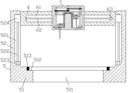
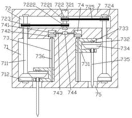
[0025] like Figure 1-Figure 6As shown, a plate punching device capable of automatically switching drill bits according to the present invention includes a frame body 5, a beam 6, and a punching assembly 7. The frame body 5 includes a base 51 and is fixed on the left and right sides of the top of the base 51. The column 52 of the punching assembly 7 is symmetrically provided with a first cavity 71 left and right, and a second cavity 72 is provided in the wall of the punching assembly 7 above the first cavity 71, and the left and right sides The inner wall of the first cavity 71 is provided with guide grooves 73 extending up and down, and the wall of the punching assembly 7 above each guide groove 73 is provided with a transmission chamber 74, and each of the first cavity A cavity 71 is provided with a first rotating shaft 711 extending up and down on the side away from the guide groove 73, and the top extension section of the first rotating shaft 711 runs through the inner top...


PUM


Abstract

The invention discloses a plate punching device capable of automatically replacing drill bits. The device comprises a frame body, a cross beam and a punching assembly; the frame body includes a base, and stand columns fixed on the left and right sides of the top of the base; first cavities are arranged in the punching assembly in a bilateral symmetry manner; a second cavity is formed at the part, above the first cavities, in the wall body of the punching assembly; guide grooves arranged in a manner of extending up and down are respectively formed in the inner side walls of the first cavities on the left and right sides; transmission cavities are formed in the parts, above the guide grooves, in the wall body of the punching assembly; first rotating shafts arranged in a manner of extending up and down are arranged on the sides, far away from the guide grooves, of the first cavities; the top extension sections of the first rotating shafts penetrate through the inner top walls of the first cavities and extend into the second cavity; first bevel gears are fixedly arranged on the outer surfaces of the parts, positioned at the bottoms of the first cavities, of the first rotating shafts; a second rotating shaft is arranged in the center position of the inner wall of the second cavity; and the top of the second rotating shaft is connected with a first motor in a matched manner. The device is simple in structure, reasonable in design and convenient to operate, improves the punching efficiency, and is stable in operation and high in precision.

Description

technical field [0001] The invention relates to the technical field of plate processing, in particular to a plate punching device capable of automatically switching drill bits. Background technique [0002] At present, due to its convenient processing and certain strength, plates are widely used in our production and life, and are closely related to each of us. Plates are used by us to build houses, decorate indoor environments, and make indoor furniture. In the process, especially the processing of wood boards, it is necessary to punch holes in the wood boards according to the needs. The traditional wood board punching device generally uses the worker to hold the punching head to punch the wood boards. The labor intensity of the workers is relatively high, and the work efficiency Low, especially when it is necessary to punch multiple round holes at equal intervals on a wooden board, due to the randomness of the worker's operation, it is difficult to accurately punch holes o...

Claims


Application Information

Patent Timeline
IPC IPC(8): B27C3/02
CPCB27C3/02
Inventor 刘建华
Owner 佛山市南海区澳宏家具有限公司
Why Eureka
Try Eureka