
A flue gas circulation incinerator and its incineration method

A technology of flue gas circulation and incinerator, applied in the direction of combustion method, incinerator, combustion type, etc., can solve the problems of reducing the processing capacity of the incinerator, high investment cost of infrastructure, and insufficient combustion, so as to reduce energy loss and increase temperature , The effect of sufficient material combustion

Active Publication Date: 2019-05-07
广东焕杰环保科技有限公司
View PDF9 Cites 0 Cited by
  • Summary
  • Abstract
  • Description
  • Claims
  • Application Information

AI Technical Summary

Problems solved by technology

However, breaking the material into powder greatly reduces the processing capacity of the incinerator, and the incinerator adopts electric heating to maintain the furnace body at 800-850°C, so its energy consumption is relatively high
[0006] Although there are various types of sludge incinerators at present, they all have various problems such as insufficient combustion, high energy consumption, and large infrastructure investment costs.

Method used


Image

  • A flue gas circulation incinerator and its incineration method
  • A flue gas circulation incinerator and its incineration method
  • A flue gas circulation incinerator and its incineration method

Examples


Embodiment 1

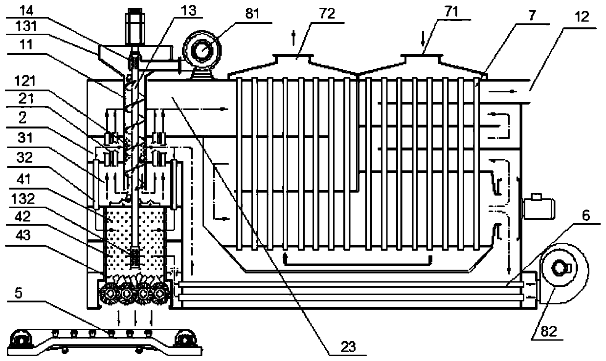
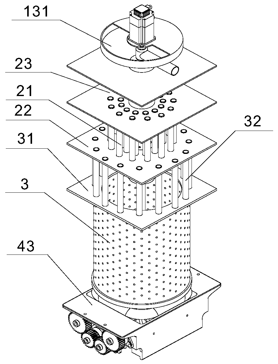
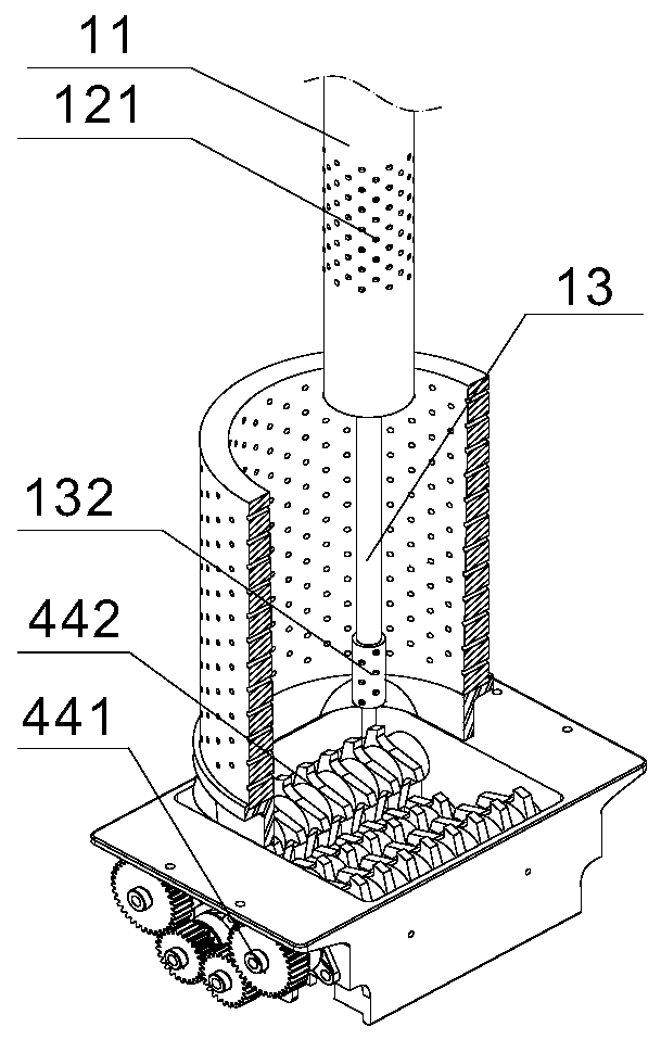
[0035] Such as Figure 1-Figure 4 As shown, the flue gas circulation incinerator provided by the present invention includes a feed system, a flue gas circulation system and a furnace 3 .

[0036]Wherein, the flue gas circulation system includes a first heat exchanger 2 , a second heat exchanger 7 and a third heat exchanger 6 . The first heat exchanger 2 and the feeding system are located on the upper part of the furnace 3, the feeding system is used to supply the dried material to the furnace 3; the first heat exchanger 2 is used to exchange between the flue gas generated by combustion and the circulating flue gas The heat and preheat the material in the feeding system. The feed system passes through the first heat exchanger 2, and the material in it is heated to 150-300°C, such as 200°C, 250°C, etc., through the first heat exchanger 2 during the process of falling into the furnace 3.

[0037] A third chamber 31 is also provided between the first heat exchanger 2 and the fur...

Embodiment 2

[0070] Such as Figure 5As shown, the flue gas circulation incinerator provided by the present invention includes a feed system, a flue gas circulation system and a furnace 3 .

[0071] Wherein, the flue gas circulation system includes a first heat exchanger 2 , a second heat exchanger 7 and a third heat exchanger 6 . The first heat exchanger 2 and the feeding system are located on the upper part of the furnace 3, the feeding system is used to supply the dried material to the furnace 3; the first heat exchanger 2 is used to exchange between the flue gas generated by combustion and the circulating flue gas of heat. The feed system passes through the first heat exchanger 2, and the material in it is heated to 150-300°C, such as 200°C, 250°C, etc., through the first heat exchanger 2 during the process of falling into the furnace 3.

[0072] The flue gas cooled by the first heat exchanger 2 enters the second heat exchanger 7 for further cooling, part of the flue gas leaves the f...


PUM


Abstract

The invention provides a flue gas circulation incinerator which comprises a feeding system, a flue gas circulation system and a hearth. The flue gas circulation system comprises a first heat exchanger, the feeding system and the first heat exchanger are located at the upper portion of the hearth, the feeding system penetrates the first heat exchanger, and materials are preheated in the feeding process. The invention further provides a flue gas circulation incineration method; and the materials incinerate in a burning chamber after being preheated and carbonized, flue gas generated by incineration is subject to heat exchange to return to a carbonization chamber, materials in the flue gas are carbonized, and slag generated by carbonization is discharged out through a slag discharging chamber. The flue gas circulation incinerator is provided with multiple stages of heat exchangers, heat energy is sufficiently used, energy losses are reduced, and the furnace temperature is improved. The materials burn after carbonization in the hearth, and therefore the materials burn more sufficiently. The content of dioxins in the flue gas is controlled by controlling the burning rate and the flue gas cooling rate. Residues are discharged in the solid manner, residue caking and blocking are avoided, and stable running of the flue gas circulation incinerator is guaranteed.

Description

technical field [0001] The invention relates to a sludge incinerator, in particular to a flue gas circulation incinerator with complete sludge incineration and no secondary pollution. Background technique [0002] With the improvement of people's living standards and the gradual advancement of urbanization, the amount of sludge has increased significantly. Sludge has a wide range of sources, complex components, and difficult treatment, and the direct discharge of sewage and sludge will cause secondary pollution. [0003] At present, there are three main methods of sludge treatment: landfill, composting and incineration. Burial is a traditional sludge treatment method, which simply treats sludge, such as dewatering, drying, etc., and bury it. However, since sludge generally carries heavy metals, pathogenic bacteria, etc., simple treatment cannot eliminate them. Heavy metals and pathogenic bacteria, so burial will cause a series of follow-up problems, such as polluting groun...

Claims


Application Information

Patent Timeline
Patent Type & Authority Patents(China)
IPC IPC(8): F23G7/00
CPCF23G7/001F23G2201/10F23G2202/106F23G2206/10F23G2209/12
Inventor 张建新张嘉良
Owner 广东焕杰环保科技有限公司
Features
  • Generate Ideas
  • Intellectual Property
  • Life Sciences
  • Materials
  • Tech Scout
  • Unparalleled Data Quality
  • Higher Quality Content
  • 60% Fewer Hallucinations
Learn More