Needle cap suitable for syringe

A needle cap and cap body technology, applied in the field of medical devices, can solve the problems of meaningless waste of medicine and affecting the treatment effect, etc.

Inactive Publication Date: 2017-07-28
崔玉合
View PDF10 Cites 1 Cited by
  • Summary
  • Abstract
  • Description
  • Claims
  • Application Information

AI Technical Summary

Problems solved by technology

However, the emptying process will cause meaningless waste of medicine, making the actual dose injected into the patient's body less than the expected dose, affecting the therapeutic effect

Method used


Image

  • Needle cap suitable for syringe
  • Needle cap suitable for syringe
  • Needle cap suitable for syringe

Examples


Embodiment

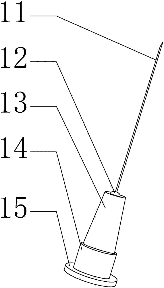
[0039] Embodiment: a kind of needle cap that is applicable to syringe, its structure is as Figure 2-6 shown, including:

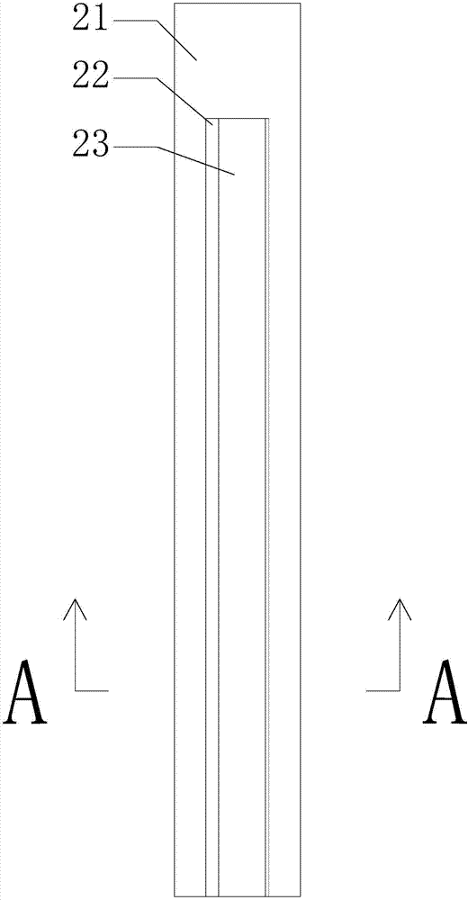
[0040] The cap body 21, the cap body 21 is a hollow cylindrical structure;

[0041] The top of the cap body 21 is a closed structure, and the bottom is an open structure;

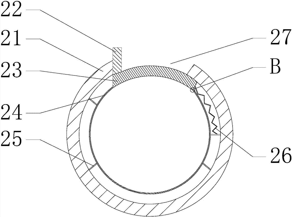
[0042] The side of the cap body 21 has a first through groove 27;

[0043] The inner wall of the cap body 21 is fixedly connected with the sleeve 24 through four connecting plates 25;

[0044] The top of the sleeve 24 is a closed structure, and the bottom is an open structure;

[0045] The side of the sleeve 24 has a second through groove 28;

[0046] The first through-slot 27 and the second through-slot 28 together become a channel for the needle piercing part to enter the inside of the cap body 21 .

[0047] An arc-shaped baffle 23 for closing the first through groove 27 is arranged between the sleeve 24 and the cap body 21, and one side (exposed side) of the arc-shaped baffle 23...


PUM


Abstract

The invention relates to a needle cap suitable for a syringe and belongs to the technical field of medical instruments. The needle cap mainly includes a hollow cylindrical cap body, the top of the cap body is of a closed structure, and the bottom of the cap body is of an open structure; the side portion of the cap body is provided with a through groove, the inner wall of the cap body is fixedly connected with a sleeve pipe through a connecting plate, the top of the sleeve pipe is of a closed structure, and the bottom of the sleeve pipe is of an open structure; the side portion of the sleeve pipe is provided with a second through groove, an arc-shaped baffle used for sealing the first through groove is arranged between the sleeve pipe and the cap body, and one side of the arc-shaped baffle is fixedly connected with a straight baffle; the other side of the arc-shaped baffle is fixedly connected with one end of an elastic part, and the other end of the elastic part is fixedly connected with the connecting plate; the straight baffle protrudes out of the cap body. By designing a novel structure, the situation that medical-care personnel is stabbed in the sleeving process can be avoided, and the risk that a puncture part scratches plastic particles on the needle cap can be avoided.

Description

technical field [0001] The invention relates to the relevant technical field of medical equipment, in particular to a needle cap suitable for a syringe. Background technique [0002] Syringes are one of the common medical devices. It generally includes a needle cap, a needle head, a cylinder body and a piston, and the needle cap and the needle head are snapped together. [0003] refer to figure 1 As shown, the existing needle head includes the puncture part 11 , the connecting part 12 , the diameter reducing part 13 , the equal diameter part 14 and the convex part 15 from top to bottom. Among them, the puncture part 11 is airtightly connected with the variable diameter part 13 through the connecting part 12, the variable diameter part 13 is convenient for the fastening of the needle cap, the equal diameter part 14 is used to limit the position during the fastening process of the needle cap, and the convex part 15 is convenient for the needle from Remove from cylinder. ...

Claims


Application Information

Patent Timeline
Patent Type & Authority Applications(China)
IPC IPC(8): A61M5/32
CPCA61M5/3202A61M5/3216
Inventor 崔玉合
Owner 崔玉合
Why Eureka
Try Eureka