Microscopic scanning automatic focusing compensation system and compensation method

An automatic focus and compensation system technology, applied in microscopes, optics, instruments, etc., can solve problems such as low efficiency and time wasting, and achieve the effect of reducing deviation and moving efficiently and quickly

Pending Publication Date: 2017-08-01
南京东利来光电实业有限责任公司
View PDF7 Cites 1 Cited by
  • Summary
  • Abstract
  • Description
  • Claims
  • Application Information

AI Technical Summary

Problems solved by technology

[0005] This focusing process is obviously a waste of time, especially when the size of the object is large, the efficiency is lower

Method used


Image

  • Microscopic scanning automatic focusing compensation system and compensation method
  • Microscopic scanning automatic focusing compensation system and compensation method

Examples


Embodiment Construction

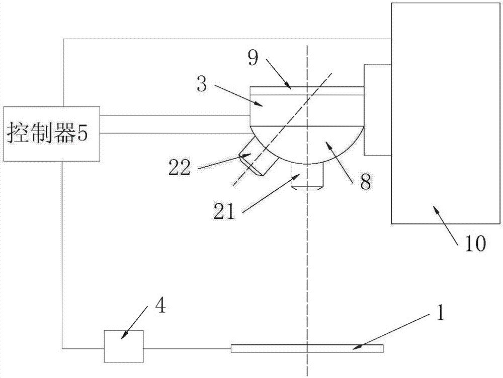
[0025] see figure 1 The microscopic scanning autofocus compensation system shown includes a stage 1 that can be along the x-axis direction and the y-axis direction in the horizontal plane, and objective lenses 21 and 22 for imaging objects on the stage are arranged above the stage , a fast focus module 3 and a position detection device 4 for real-time detection of the position of the stage on the x-axis and y-axis, a controller 5, an electric nose wheel 8, a bracket 9, and a bracket lifting electric drive device 10.

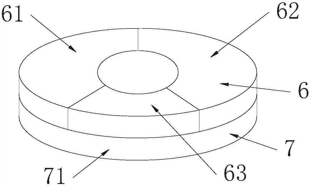
[0026] The fast focusing module 3 includes an optical axis tilt compensation module 6 and a focus z-axis deviation compensation module 7 .

[0027] The optical axis inclination compensation module 6 is three sector-shaped piezoelectric ceramics 61, 62, 63 that have an inverse piezoelectric effect and can be extended or shortened in the z-axis direction, and are used to respectively supply power to the three sector-shaped piezoelectric ceramics to Three tilt comp...


PUM


Abstract

The invention provides a microscopic scanning automatic focusing compensation system and method so that focusing time can be shortened and the microscopic scanning efficiency can be enhanced. The focusing compensation system comprises an object table, an object lens, a quick focusing module and a position detection device used for detecting the position of the object table in real time. The quick focusing module comprises z-axis compensation piezoelectric ceramic which is capable of extending or shortening in the z-axis direction and a z-axis compensation voltage module which supplies power to the z-axis compensation piezoelectric ceramic. The upper end of the object lens is connected with the z-axis compensation piezoelectric ceramic. The output of the position detection device is connected with a controller which is connected with the z-axis compensation voltage module. According to the focusing compensation method, firstly the distance t from any point a (x, y) on the object table to the focal plane of the object lens is measured; and the external electric field voltage of the z-axis compensation piezoelectric ceramic is controlled through the controller in use so that the object lens is enabled to move along the z-axis under driving of the z-axis compensation piezoelectric ceramic, the focal plane and any point a (x, y) are enabled to be overlapped and thus automatic quick compensation of focus z-axis deviation can be realized.

Description

technical field [0001] The technology relates to a microscanning automatic focus compensation system and a compensation method. Background technique [0002] In micro-scanning, the object to be scanned is placed on the stage, and through the movement of the x-axis and y-axis of the stage, the object passes through the focal plane of the objective lens in turn, and the object space passes through the objective lens. Each point on the object is imaged separately, and then the images of each point are stitched together to form the image of the entire object space. [0003] Due to the manufacturing error of the stage, the influence of the use environment, etc., during the scanning process, when each point a(x, y) of the stage moves below the objective lens, the point a(x, y) may deviate from the focal plane of the objective lens , in order to obtain a clear image at this time, it is necessary to re-focus. [0004] The method of refocusing is generally to take 40 images of poin...

Claims


Application Information

Patent Timeline
Patent Type & Authority Applications(China)
IPC IPC(8): G02B21/00
CPCG02B21/006
Inventor 张辉
Owner 南京东利来光电实业有限责任公司
Why Eureka
Try Eureka