Automatic horizontal projectile motion demonstration device

A demonstration device and technology of flat throwing, applied in the field of teaching aids, can solve problems such as complicated steps, inability for students to intuitively understand the characteristics of flat throwing motion, and lack of intuitiveness and continuity in the experimental operation process, so as to achieve the effect of deepening students' impression

Inactive Publication Date: 2017-08-01
李子衿
View PDF6 Cites 10 Cited by
  • Summary
  • Abstract
  • Description
  • Claims
  • Application Information

AI Technical Summary

Problems solved by technology

[0003] The traditional flat-throwing motion demonstration instrument is more complicated and cumbersome to operate, and it is time-consuming to demonstrate and explore in the classroom. In reality, there are many demonstration devices that use flat-throwing motion experiments. For example, the utility model patent with the publication number CN203232611U discloses a The mechanical energy conservation flat throwing motion experimenter includes an upper cover plate, a rear fixing block is arranged under the rear part of the upper cover plate, and a scale block is installed at the rear end of the upper cover plate, which can slide horizontally above the upper cover plate, and the horizontal scale is attached to the On the upper part of the U-shaped track, there is a front fixing block under the front of the upper cover, adjustment knobs are arranged on both sides of the front fixing block, a flat throwing sensor is inserted in the front groove of the upper cover, and the end of the vertical fixing rod extends into the upper cover In the front fixing block under the front part of the plate, there is a photoelectric door fixing rod on the back of the scale plate. The edge is connected with the arc track fixing seat
[0004] Although the above-mentioned experimental device can relatively increase the yield, high quali

Method used


Image

  • Automatic horizontal projectile motion demonstration device
  • Automatic horizontal projectile motion demonstration device
  • Automatic horizontal projectile motion demonstration device

Examples


Embodiment Construction

[0027] In order to make the purpose, technical solutions and advantages of the present invention clearer, the technical solutions in the embodiments of the present invention will be clearly and completely described below in conjunction with the accompanying drawings in the embodiments of the present invention. Obviously, the described embodiments are the Some, but not all, embodiments are invented. Based on the embodiments of the present invention, all other embodiments obtained by persons of ordinary skill in the art without creative efforts fall within the protection scope of the present invention.

[0028] In the present invention, the terms "upper", "lower", "left", "right", "front", "rear", "top", "bottom", "inner", "outer", "middle", The orientations or positional relationships indicated by "vertical", "horizontal", "horizontal", and "longitudinal" are based on the orientations or positional relationships shown in the drawings. These terms are mainly used to better desc...


PUM


Abstract

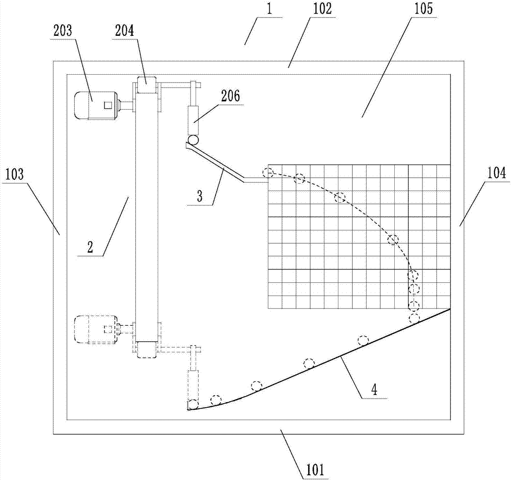
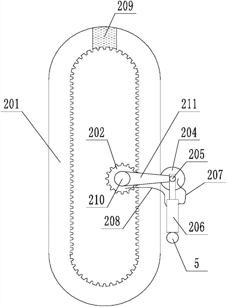
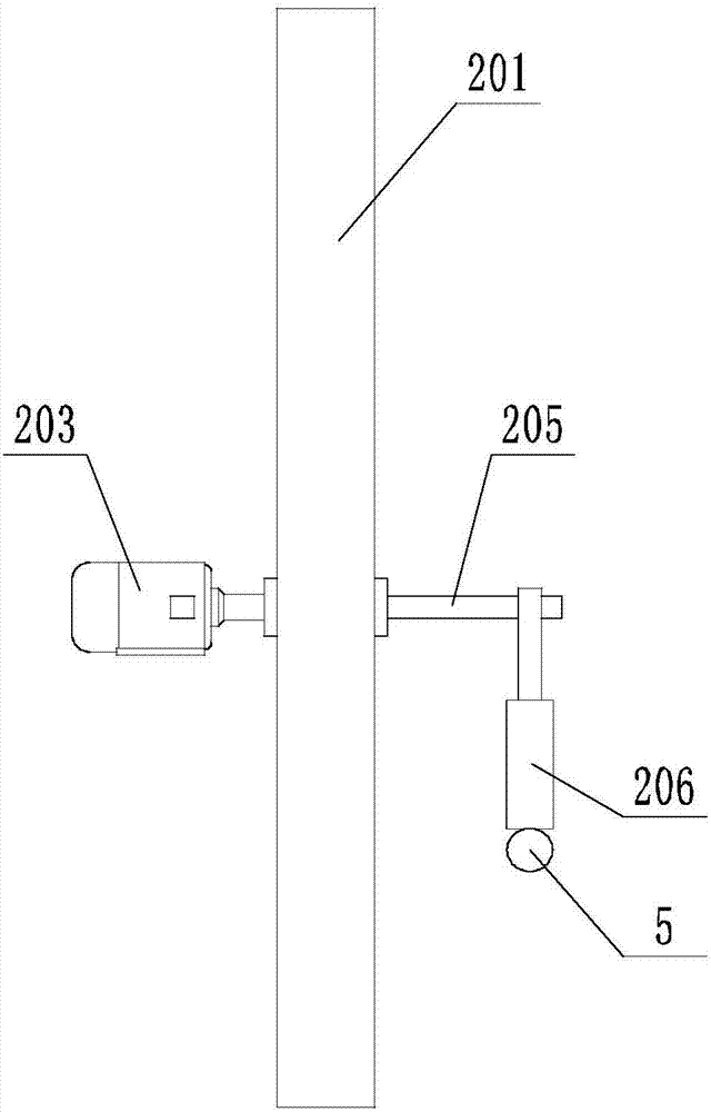
The invention belongs to the teaching aid technology field, and relates to an automatic horizontal projectile motion demonstration device. The automatic horizontal projectile motion demonstration device comprises a frame; a lifting device, a horizontal projectile track, and a bead recovery skewed slot, which are fixedly disposed on the frame. The horizontal projectile track is used to provide initial velocities of beads carrying out the horizontal projectile motion, and the bead recovery skewed slot is used to collect the beads finishing the horizontal projectile motion. The lifting device is used to lift the beads in the bead recovery skewed slot to the horizontal projectile track, and then the beads can be used to complete the horizontal projectile process again. The beads thrown by the horizontal projectile track are collected by the bead recovery skewed slot, and are lifted to the horizontal projectile track by the lifting device, and the above mentioned process can be repeated continuously, and therefore hands of experimenters are liberated, and by adopting an automatic structural design, the experiments can be carried out by throwing the beads automatically for a plurality of times. The experiments are visual and continuous, and impressions of students are deepened.

Description

technical field [0001] The invention belongs to the technical field of teaching tools, and relates to an automatic demonstration device for flat throwing motion. Background technique [0002] In physical experimental devices, especially mechanical experimental devices, it is often involved in demonstrating the motion law of flat throwing motion. We all know that there is a special case in the projectile motion, when the object is thrown, the initial velocity direction is along the horizontal direction, that is, the object has a horizontal initial velocity, and the curved motion only under the action of gravity is called flat throwing motion. When analyzing the flat throwing movement, we can decompose the flat throwing movement into two sub-movements in the horizontal direction and the vertical direction. The motion in the horizontal direction is a uniform linear motion, and the vertical direction is a free fall motion. In order to study the law of flat throwing motion in p...

Claims


Application Information

Patent Timeline
IPC IPC(8): G09B23/10
Inventor 李子衿
Owner 李子衿
Why Eureka
Try Eureka