Isolation switch apparatus

A technology of isolating switch and arc extinguishing device, which is used in electrical switches, high-voltage/high-current switches, high-voltage air circuit breakers, etc. Maintenance and other issues, to achieve the effect of simple structure, avoiding arc burning of electrical appliances, and low cost

Inactive Publication Date: 2017-08-01
林向阳
View PDF0 Cites 0 Cited by
  • Summary
  • Abstract
  • Description
  • Claims
  • Application Information

AI Technical Summary

Problems solved by technology

[0002] After most of the rural and remote areas in China have been electrified one after another, most of the high-voltage isolating switches, short circuit breakers and other electrical equipment have been placed outdoors for a long time, and are distributed in various streets, urban-rural junctions, rural areas and other places, which cannot be managed and maintained uniformly. Inadequate, damage to adjacent electrical equipment due to excessive temperature during operation
[0003] At present, the isolating switch is a kind of control switch with the simplest structure and widely used in the hand-controlled electrical appliances. The main function is to isolate the power supply to ensure the safety of circuit and equipment maintenance and to break the load. However, due to the imperfect design of the existing isolating switch, it has the following defects: First, it is used in medium and high voltage circuits. The current is large, and a high-energy arc will be generated at the same time of breaking, which will pose a great danger to the equipment. Second, in some special environments, it is necessary to fine-tune the position of the insulating porcelain bottle, but due to They are all fixed together and cannot be adjusted, so they are less practical

Method used


Image

  • Isolation switch apparatus
  • Isolation switch apparatus
  • Isolation switch apparatus

Examples


Embodiment Construction

[0022] In order to make the technical means, creative features, objectives and beneficial effects realized by the present invention easy to understand, the present invention will be further described below in conjunction with specific embodiments.

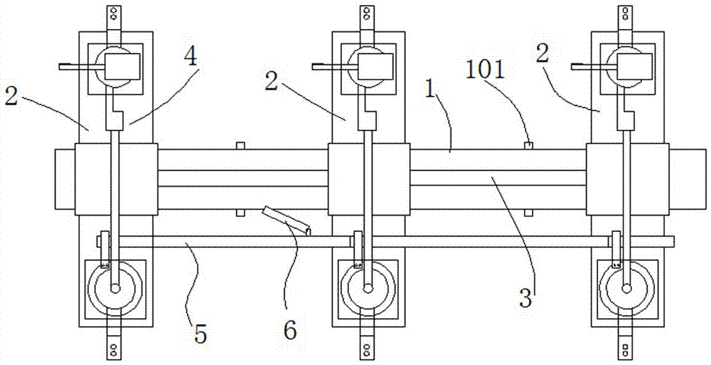
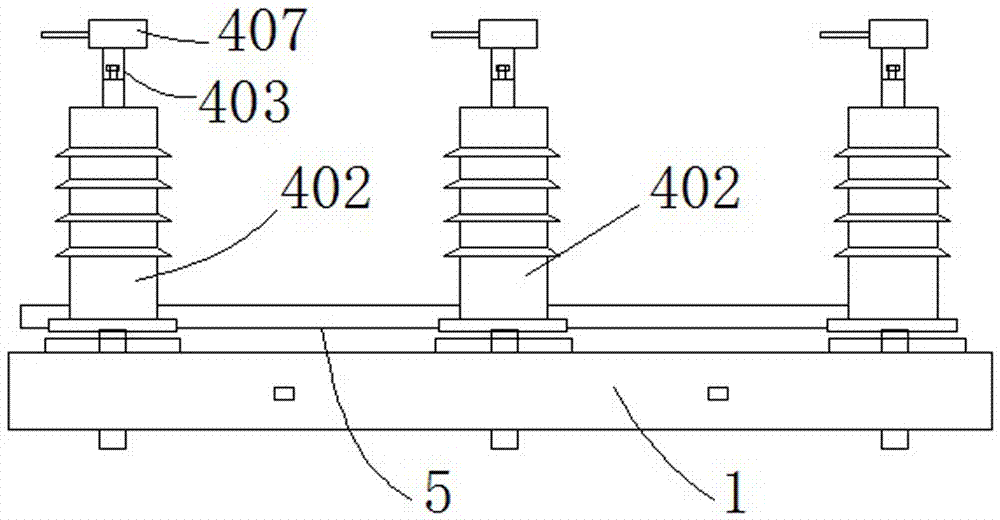
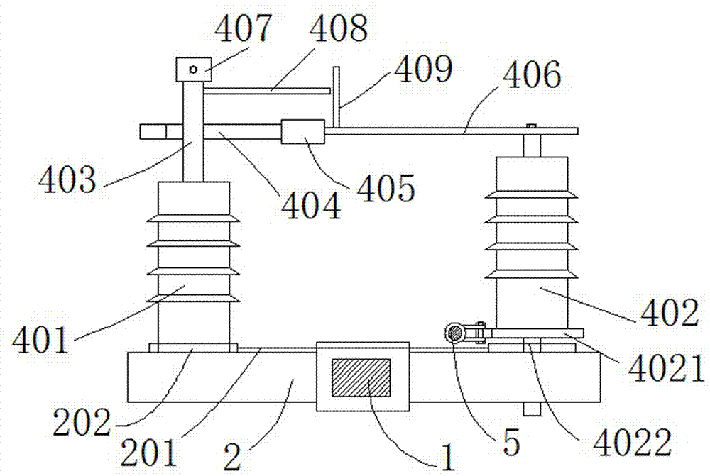
[0023] As shown in the figure, an isolating switch device includes a bracket 1 and several arc extinguishing devices 4 arranged on the bracket. The bracket 1 is also provided with several sliding parts that are sleeved on the bracket and perpendicular to the bracket. Vertical plate 2, the middle part of the sliding vertical plate 2 is provided with a mounting hole, the sliding vertical plate 2 is sleeved on the bracket 1 through the mounting hole, and a width adjustment mechanism 3 is provided between any two sliding vertical plates. Before the actual installation on the high-voltage line, the distance between any two sliding risers 3 can be adjusted through the width adjustment mechanism according to the actual situation. A guide r...


PUM


Abstract

An isolating switch device, including a bracket and several arc extinguishing devices arranged on the bracket, and also includes several sliding risers sleeved on the bracket and perpendicular to the bracket, the middle part of the sliding riser is provided with a mounting hole, the sliding vertical plate is sleeved on the bracket through the mounting hole, a width adjustment mechanism is provided between any two sliding vertical plates, and an arc extinguishing device is correspondingly provided on each sliding vertical plate. The device comprises a fixed insulating porcelain bottle arranged at one end of a sliding vertical plate, a rotating insulating porcelain bottle arranged at the other end of a sliding vertical plate, and a disconnection control device arranged between the fixed insulating porcelain bottle and the rotating insulating porcelain bottle. Compared with the prior art, the present invention , By optimizing the installation position of the arc extinguishing chamber, the overall safety performance of the device is improved, and by optimizing the main structure of the bracket, the practicability is also greatly improved.

Description

technical field [0001] The invention relates to a switch device used on a high-voltage line, in particular to an isolating switch device. Background technique [0002] After most of the rural and remote areas in China have been electrified, most of the high-voltage isolating switches, short circuit breakers and other electrical equipment have been placed outdoors for a long time, and are distributed in various streets, urban-rural junctions, rural areas, etc., and cannot be managed and maintained uniformly. If it is not good, it will damage the adjacent electrical equipment due to excessive temperature during operation. [0003] At present, the isolating switch is a kind of control switch with the simplest structure and widely used in hand-controlled electrical appliances. It is mainly used for infrequently connecting and breaking low-voltage circuits with small capacity or directly starting small-capacity motors. The main function is to isolate the power supply to ensure t...

Claims


Application Information

Patent Timeline
Patent Type & Authority Applications(China)
IPC IPC(8): H01H33/02H01H33/42H01H33/72
CPCH01H33/02H01H33/42H01H33/72
Inventor 林向阳
Owner 林向阳
Why Eureka
Try Eureka