Electric-control feeding clamping device

A clamping device, electronically controlled technology, applied in the direction of conveyors, conveyor objects, transportation and packaging, etc., to achieve the effect of being simple and easy to implement, easy to promote and apply, and to reduce the traction load

Inactive Publication Date: 2016-09-07
ANQING TIANRUN ENG MACHINERY
View PDF10 Cites 0 Cited by
  • Summary
  • Abstract
  • Description
  • Claims
  • Application Information

AI Technical Summary

Problems solved by technology

[0004] In view of this, it is necessary to provide an electronically controlled feeding clamping device, which solves the problem of smooth feeding of cylinders with different diameters

Method used


Image

  • Electric-control feeding clamping device
  • Electric-control feeding clamping device
  • Electric-control feeding clamping device

Examples


Embodiment Construction

[0016] In order to make the objectives, technical solutions and advantages of the present invention clearer, the following further describes the present invention in detail with reference to the accompanying drawings and embodiments. It should be understood that the specific embodiments described herein are only used to explain the present invention, but not to limit the present invention.

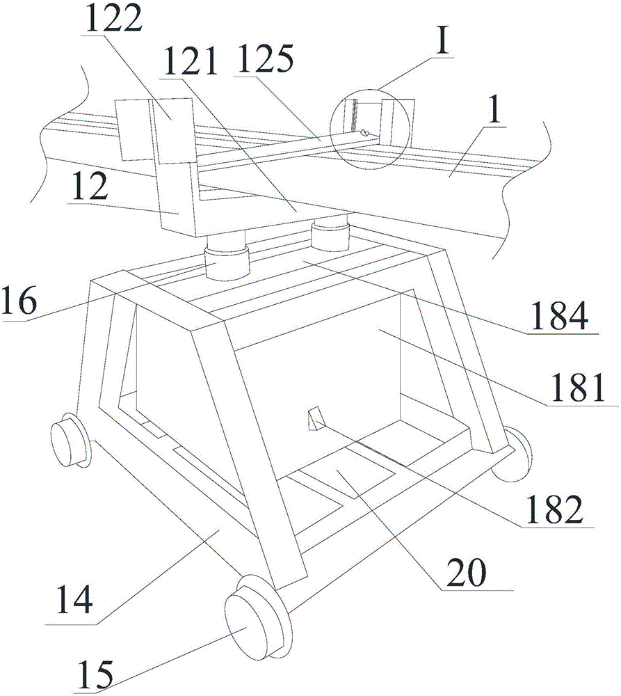
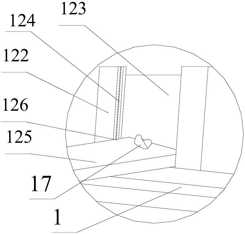
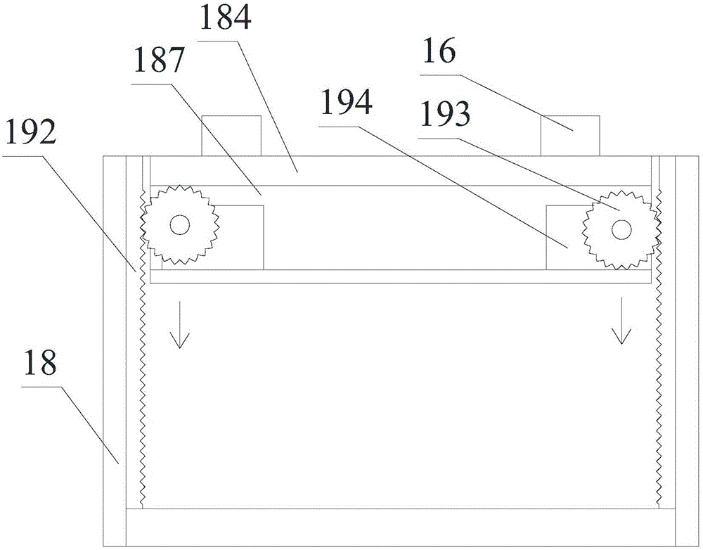
[0017] Please refer to figure 1 , figure 2 and image 3 ,among them, figure 2 for figure 1 A partial enlarged schematic diagram of the middle area I. The base 14, the supporting base 12, and the lifting mechanism of the electronically controlled feeding and clamping device of the present invention. The lifting mechanism is installed on the base 14, and the lifting mechanism is used to drive the support base 12 to lift.

[0018] The supporting base 12 includes a supporting beam 121, two limiting posts 122 and a clamping plate 125. The support beam 121 is used to support a plurality of workp...


PUM


Abstract

The invention relates to an electric-control feeding clamping device which comprises a base, a supporting seat and a lifting mechanism. The lifting mechanism comprises a box body, a supporting frame and a conveying mechanism. The box body is fixed to the base. The box body is provided with a top face capable of ascending and descending. The supporting seat is fixed to the top face. Both the supporting frame and the conveying mechanism are arranged in the box body. The supporting frame is fixed to the bottom of the top face. The conveying mechanism is integrally installed on the supporting frame. The conveying mechanism comprises two racks arranged in parallel, two rotary wheels engaged with the two racks correspondingly, and two motors used for driving the two rotary wheels to rotate oppositely and synchronously. The supporting seat comprises a clamping plate, a supporting beam used for supporting a plurality of workpieces to be positioned, and two limiting columns fixed to the two opposite ends of the supporting beam. The clamping plate is locked to the supporting beam through a plurality of bolts so that the multiple workpieces to be positioned can be clamped on the supporting beam, wherein a butterfly-shaped operating part is located at the top of each bolt.

Description

Technical field [0001] The invention relates to a clamping device in the production process of a workpiece, in particular to an electronically controlled feeding clamping device. Background technique [0002] In the production process of the workpiece, such as the production process of the piston rod, the cylinder barrel must first be cut to the required size. Because the cylinder barrel is long and heavy, it is not convenient for manual handling and a feeding device is required. Some feeding devices do not have a clamping device, and the cylinder barrel is unstable during transportation, which poses a safety hazard. Even with some clamping devices, the width cannot be adjusted according to the number of cylinders. Some feeding devices transport less materials at a time and have low efficiency. Some blanking machines need to use cold water to pour the cutting part to cool down during the cutting process, but the cooling water will trickle down the cutting part to the other end ...

Claims


Application Information

Patent Timeline
IPC IPC(8): B65G47/74
CPCB65G47/74B65G2201/02
Inventor 吴琪李乾龙
Owner ANQING TIANRUN ENG MACHINERY
Why Eureka
Try Eureka