Feeding supporting electric-control lifting device

A lifting device and electronic control technology are applied in the directions of conveyors, supporting frames, conveyor objects, etc., to achieve the effects of low cost, simple structure, and easy promotion and application.

Inactive Publication Date: 2016-09-07
ANQING TIANRUN ENG MACHINERY
View PDF10 Cites 0 Cited by
  • Summary
  • Abstract
  • Description
  • Claims
  • Application Information

AI Technical Summary

Problems solved by technology

[0004] In view of this, it is necessary to provide an electronically controlled lifting device for feeding support, which solves the problem of smooth feeding of cylinders with different diameters

Method used


Image

  • Feeding supporting electric-control lifting device
  • Feeding supporting electric-control lifting device

Examples


Embodiment Construction

[0016] In order to make the object, technical solution and advantages of the present invention more clear, the present invention will be further described in detail below in conjunction with the accompanying drawings and embodiments. It should be understood that the specific embodiments described here are only used to explain the present invention, not to limit the present invention.

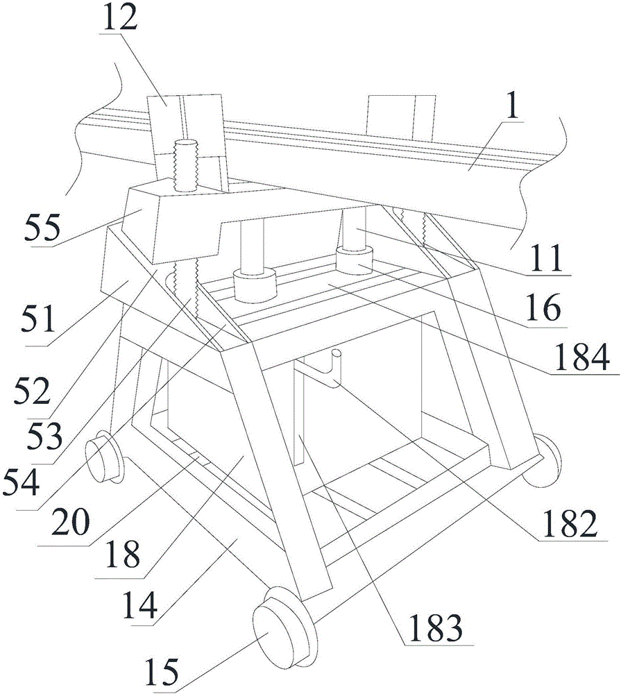
[0017] Please also refer to figure 1 and figure 2 , The feeding support electronically controlled lifting device of the present invention includes a base 14, a support base 12, and a lifting mechanism. The lifting mechanism is installed on the base 14, and the lifting mechanism is used to drive the support base 12 to lift. The bottom of the base 14 can be provided with some pulleys 15, so that it is convenient to move the whole feeding support electric control lifting device.

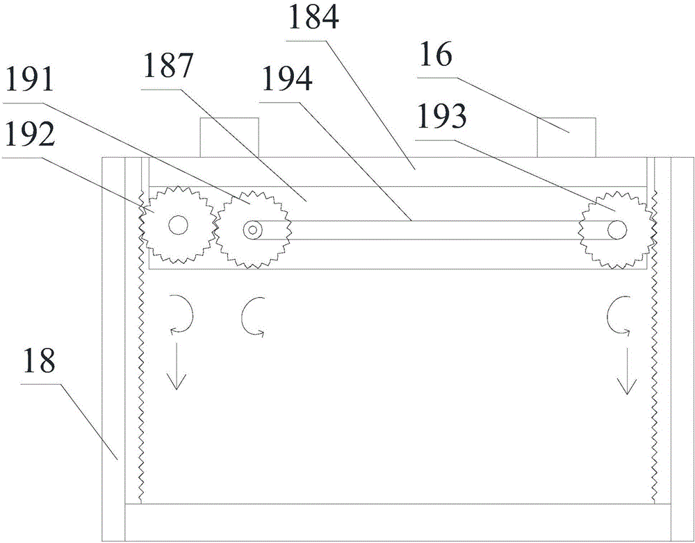
[0018] The lifting mechanism includes a wedge block 51, a driver, a threaded rod 53, a casing 18, a support frame 1...


PUM


Abstract

The invention relates to a feeding supporting electric-control lifting device which comprises a base, a supporting seat and a lifting mechanism. The lifting mechanism comprises wedge-shaped blocks, a driver, threaded rods, a box body, a supporting frame and a conveying mechanism. The box body is fixed to the base. The supporting seat is fixed to the top face of the box body. Both the supporting frame and the conveying mechanism are arranged in the box body. The supporting frame is fixed to the bottom of the top face. The conveying mechanism is integrally installed on the supporting frame. The conveying mechanism comprises a driving wheel, a first driven wheel, a second driven wheel and a conveying belt. An operating crank is arranged in the rotating center of the driving wheel. Each wedge-shaped block is provided with a wedge-shaped face. A notch used for allowing the corresponding threaded rod to penetrate through is formed in each wedge-shaped face. One end of each threaded rod is inserted into the base in a penetrating mode and driven by the driver to rotate, and the other end of the threaded rod penetrates through the corresponding notch and is screwed in the supporting seat. The supporting seat is provided with oblique faces matched with the wedge-shaped faces. The wedge-shaped blocks are arranged between the base and the supporting seat in a matched mode.

Description

technical field [0001] The invention relates to a support device in the production process of workpieces, in particular to an electric control lifting device for feeding support. Background technique [0002] In the production process of the workpiece, such as the production process of the piston rod, the cylinder needs to be cut to the required size first. Because the cylinder is long and heavy, it is not convenient for manual handling, and a feeding device is required. Some feeding devices do not have a clamping device, and the cylinder barrel is not stable during transportation, which poses a safety hazard. Even if some clamping devices are installed, the width cannot be adjusted according to the number of cylinders. Some feeding devices transport less material at one time and have low efficiency. Some blanking machines need to irrigate the cutting part with cold water in order to cool down during the cutting process, but the cooling water will drip along the cutting pa...

Claims


Application Information

Patent Timeline
IPC IPC(8): B65G41/00B65G15/28
CPCB65G41/003B65G15/28B65G41/008B65G2201/0214
Inventor 吴琪李乾龙
Owner ANQING TIANRUN ENG MACHINERY
Why Eureka
Try Eureka