Device comprising a transmission assembly having an override clutch with a freewheeling member

A technology of overrunning clutches and transmissions, which is applied to transmissions, power devices inside switches, mechanical equipment, etc., and can solve problems that affect the service life of equipment and damage mechanical loads

Active Publication Date: 2017-08-01
SIEMENS ENERGY GLOBAL GMBH CO & KG
View PDF3 Cites 2 Cited by
  • Summary
  • Abstract
  • Description
  • Claims
  • Application Information

AI Technical Summary

Problems solved by technology

Such pulses cause damage and additional mechanical loads inside the device, which can affect the service life of the device

Method used


Image

  • Device comprising a transmission assembly having an override clutch with a freewheeling member
  • Device comprising a transmission assembly having an override clutch with a freewheeling member
  • Device comprising a transmission assembly having an override clutch with a freewheeling member

Examples


Embodiment Construction

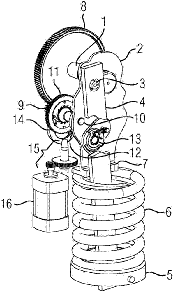
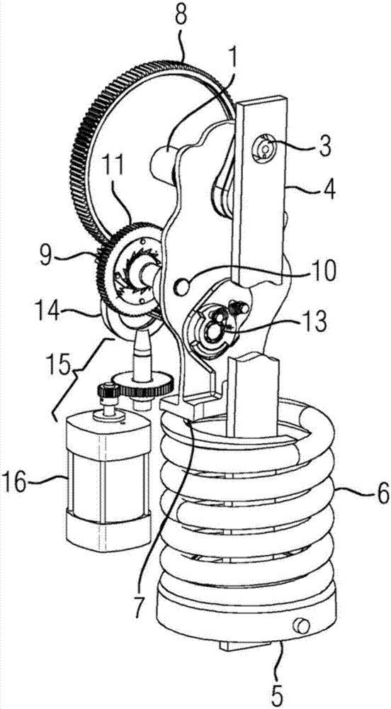
[0045] figure 1 A device comprising a transmission with a clamping shaft 1 is shown. The clamping shaft 1 is mounted rotatably in a transmission housing 2 . For better clarity, the transmission housing 2 is shown in section. The clamping shaft 1 itself is mounted rotatably in the transmission housing 2 in such a way that it is freely rotatable not only in the clockwise direction but also in the counterclockwise direction. The clamping shaft 1 is also equipped with a crank arm 3 . The connecting rod 4 is mounted on the crank arm 3 . The connecting rod 4 has a connecting rod stop 5 . The energy storage spring 6 rests against the connecting rod stop 5 . The energy storage spring 6 is here a helical spring which is passed through by the connecting rod 4 . The connecting rod stop 5 bears against the end-side end of the energy storage spring 6 . Via the other end of the energy storage spring 6 lying on the opposite end side, the energy storage spring 6 bears against the suppo...


PUM


Abstract

A device comprises a transmission assembly having a first override clutch (17b). The first override clutch (17) is used especially for transmitting torque between a first coupling partner (17a) and a second coupling partner (17b). The first override clutch (17) engages and disengages in accordance with a change in the load flow between the coupling partners (17a, 17b). A freewheeling member (19) which is associated with the first override clutch (17) neutralizes the engagement between the coupling partners (17a, 17b), especially temporarily.

Description

technical field [0001] The invention relates to a device, in particular for the transmission of reverse torque, comprising a transmission with a first overrunning clutch having a first clutch part and a second clutch part, which depend on the load flux between the clutch parts Changes engage or disengage. Background technique [0002] Such a device is known, for example, from the publication DE1134445. The document describes a device with a gear for clamping a spring force store. The transmission there is also equipped with a first overrunning clutch for torque transmission. Wherein, the overrunning clutch has a first clutch accessory and a second clutch accessory. Engagement or disengagement is effected based on changes in load flow between the clutch parts. This arrangement provides a space-saving construction, where it is possible to re-clamp the spring force store there. [0003] The overrunning clutch there has a solid structure, so it can reliably transmit high to...

Claims


Application Information

Patent Timeline
Patent Type & Authority Applications(China)
IPC IPC(8): H01H3/30H01H3/50F16H29/02H01H3/60H01H3/32F16H33/06H01H3/54
CPCF16H29/02F16H33/06H01H3/30H01H3/32H01H3/50H01H3/54H01H3/60H01H3/3021H01H3/34H01H3/58
Inventor M.巴茨O.杜韦F.勒布纳
Owner SIEMENS ENERGY GLOBAL GMBH CO & KG
Why Eureka
Try Eureka