Equipment including transmissions with overrunning clutches and freewheel members

一种超越离合器、传动装置的技术,应用在传动装置、开关内部的动力装置、机械设备等方向,能够解决破坏机械载荷、影响设备使用寿命等问题

Active Publication Date: 2019-08-09
SIEMENS ENERGY GLOBAL GMBH & CO KG
View PDF3 Cites 0 Cited by
  • Summary
  • Abstract
  • Description
  • Claims
  • Application Information

AI Technical Summary

Problems solved by technology

Such pulses cause damage and additional mechanical loads inside the device, which can affect the service life of the device

Method used


Image

  • Equipment including transmissions with overrunning clutches and freewheel members
  • Equipment including transmissions with overrunning clutches and freewheel members
  • Equipment including transmissions with overrunning clutches and freewheel members

Examples


Embodiment Construction

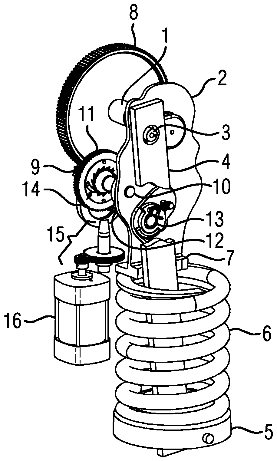
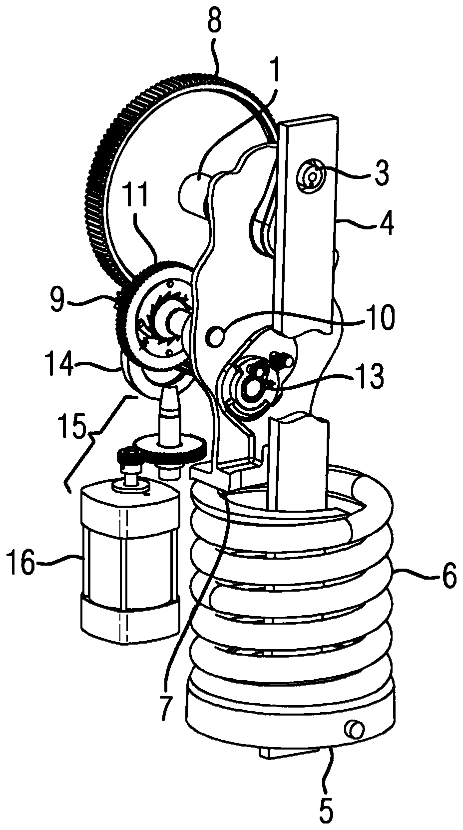
[0045] figure 1 A device comprising a transmission with a clamping shaft 1 is shown. The clamping shaft 1 is mounted rotatably in a transmission housing 2 . For better clarity, the transmission housing 2 is shown in section. The clamping shaft 1 itself is mounted rotatably in the transmission housing 2 in such a way that it is freely rotatable not only in the clockwise direction but also in the counterclockwise direction. The clamping shaft 1 is also equipped with a crank arm 3 . The connecting rod 4 is mounted on the crank arm 3 . The connecting rod 4 has a connecting rod stop 5 . The energy storage spring 6 rests against the connecting rod stop 5 . The energy storage spring 6 is here a helical spring which is passed through by the connecting rod 4 . The connecting rod stop 5 bears against the end-side end of the energy storage spring 6 . Via the other end of the energy storage spring 6 lying on the opposite end side, the energy storage spring 6 bears against the suppo...


PUM


Abstract

An apparatus comprising a transmission with a first overrunning clutch (17b). The first overrunning clutch (17) is used in particular to transmit torque between the first clutch part (17a) and the second clutch part (17b). Engagement or disengagement of the first overrunning clutch (17) is effected according to a change in the load flow between the clutch parts (17a, 17b). A freewheel element (19) is assigned to the first clutch part (17a), which deactivates, in particular temporarily, the engagement of the clutch parts (17a, 17b).

Description

technical field [0001] The invention relates to a device, in particular for the transmission of reverse torque, comprising a transmission with a first overrunning clutch having a first clutch part and a second clutch part, which depend on the load flux between the clutch parts Changes engage or disengage. Background technique [0002] Such a device is known, for example, from the publication DE1134445. The document describes a device with a gear for clamping a spring force store. The transmission there is also equipped with a first overrunning clutch for torque transmission. Wherein, the overrunning clutch has a first clutch accessory and a second clutch accessory. Engagement or disengagement is effected based on changes in load flow between the clutch parts. This arrangement provides a space-saving construction, where it is possible to re-clamp the spring force store there. [0003] The overrunning clutch there has a solid structure, so it can reliably transmit high to...

Claims


Application Information

Patent Timeline
Patent Type & Authority Patents(China)
IPC IPC(8): H01H3/30H01H3/50F16H29/02H01H3/60H01H3/32F16H33/06H01H3/54
CPCF16H29/02F16H33/06H01H3/30H01H3/32H01H3/50H01H3/54H01H3/60H01H3/3021H01H3/34H01H3/58
Inventor M.巴茨O.杜韦F.勒布纳
Owner SIEMENS ENERGY GLOBAL GMBH & CO KG
Why Eureka
Try Eureka