
Methods for multi-user MIMO wireless communication using approximation of zero-forcing beamforming matrix

A technology of wireless communication system and precoding matrix, which is applied in radio transmission system, diversity/multi-antenna system, channel coding adjustment, etc., and can solve problems such as system performance degradation

Active Publication Date: 2017-08-01
LIANG PING
View PDF3 Cites 2 Cited by
  • Summary
  • Abstract
  • Description
  • Claims
  • Application Information

AI Technical Summary

Problems solved by technology

As a result, additional approximation errors are introduced in the estimated signal in the uplink or in the transmitted signal in the downlink, they degrade the system performance

Method used


Image

  • Methods for multi-user MIMO wireless communication using approximation of zero-forcing beamforming matrix
  • Methods for multi-user MIMO wireless communication using approximation of zero-forcing beamforming matrix
  • Methods for multi-user MIMO wireless communication using approximation of zero-forcing beamforming matrix

Examples


Embodiment Construction

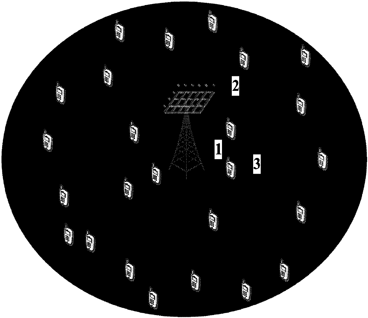
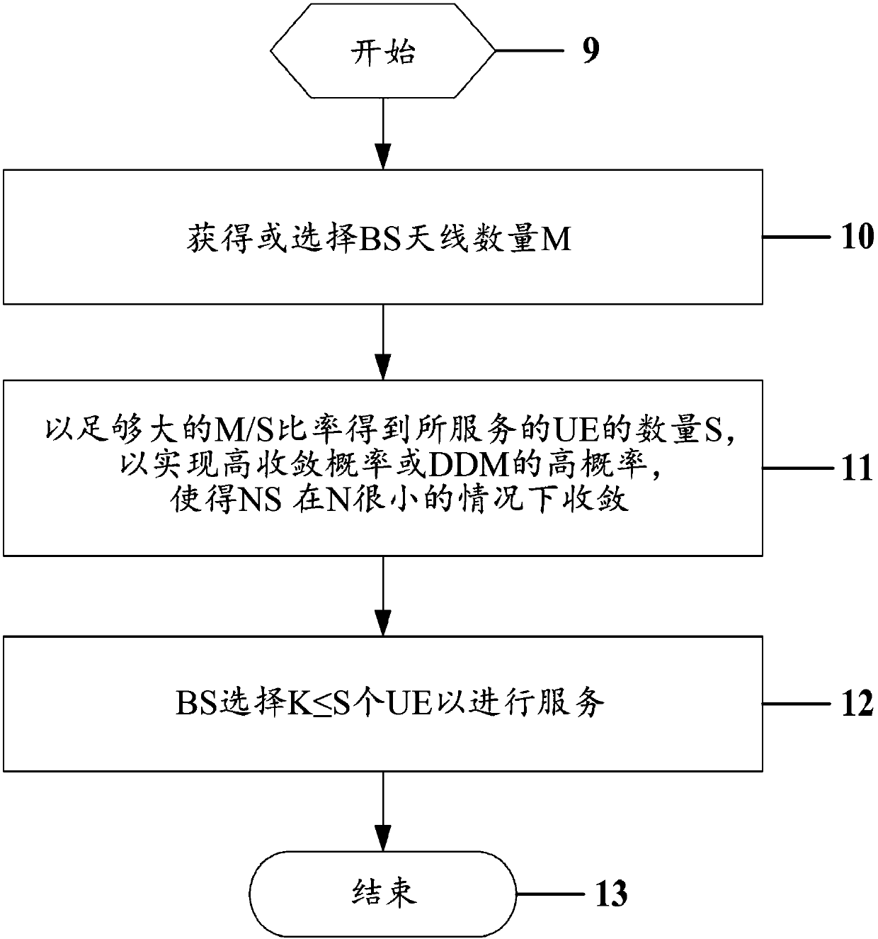
[0017] figure 1 A typical massive MU-MIMO communication system is shown, where a BS 1 is equipped with a large number of antennas 2 to serve multiple UEs 3 in the same time-frequency resource. For such systems, NS can be used to approximate the inverse matrix for the ZF-based detection method in the uplink and the precoding method in the downlink. The SIR caused by the approximation error of the AIM with various numbers of transmit-receive antennas, multiplexed UEs, and calculation process termination ranks and ranks can be calculated by formulas (1)-(4) given below. Furthermore, these values ​​can be calculated off-line and pre-stored in the memory of the BS, for example in the form of a look-up table. For example, let M, K and N represent the above three numbers respectively, where N<4, then the SIR is calculated by the following formula.

[0018]

[0019]

[0020]

[0021]

[0022] where β 1 ,β 2 ,β 3 and beta 4 is the scaling factor determined by paramete...


PUM


Abstract

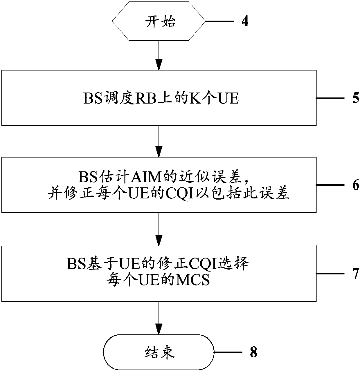
This invention presents methods for signal detection and transmission in MU-MIMO wireless communication systems, for inverse matrix approximation error calculation, for adaptively selecting the number of multiplexed UEs in a MU-MIMO group, for adaptively choosing a modulation and channel coding scheme appropriate for the quality of MU-MIMO channels with the approximation error of matrix inverse being incorporated.

Description

[0001] This application claims the benefit of US Provisional Application No. 62 / 056,489, filed September 27, 2014. technical field [0002] The field of the invention is wireless communication, and more particularly, to methods of signal detection and transmission in multi-user (MU) multiple-input multiple-output (MIMO) wireless communication systems, and in particular to methods for inverse matrix approximation error calculation, selection of MU- A method for the number of multiplexed user equipments (UEs) in a MIMO group and a method for choosing an appropriate modulation and coding scheme (MCS). Background technique [0003] In massive MIMO systems [1], each base station (BS) is equipped with tens to hundreds or thousands of antennas to serve dozens or more UEs in the same time-frequency resource. As a result, they can achieve significantly higher spatial multiplexing gains compared to traditional MU-MIMO systems, which is one of the most important advantages of massive M...

Claims


Application Information

Patent Timeline
Patent Type & Authority Applications(China)
IPC IPC(8): H04B7/0452H04B7/06
CPCH04B7/04H04B7/0452H04B7/0617H04L1/00H04L1/0003H04L1/0009H04L25/03006H04L2025/03624
Inventor 梁平朱登魁B·李
Owner LIANG PING
Learn More