Seat cover and vehicle

A technology for seats and slide rails, which is used in movable seats, vehicle parts, seat covers, etc., to improve work efficiency, protect the connection part, and improve the degree of freedom of layout.

Active Publication Date: 2017-08-04
HONDA MOTOR CO LTD
View PDF7 Cites 1 Cited by
  • Summary
  • Abstract
  • Description
  • Claims
  • Application Information

AI Technical Summary

Problems solved by technology

[0006] However, since the connecting work of the connector is performed while the sliding seat is lifted and tilted, there is a problem of improving work efficiency when connecting the floor side and the seat side.

Method used


Image

  • Seat cover and vehicle
  • Seat cover and vehicle
  • Seat cover and vehicle

Examples


Embodiment Construction

[0036] Embodiments of the present invention will be described below with reference to the drawings. In the embodiment of the present invention, a seat cover used in a vehicle will be described as an example. In the following description, directions such as front, rear, left, and right are the same as those in the vehicle unless otherwise specified. In addition, in the drawings for description below, an arrow FR indicating the front of the vehicle, an arrow LH indicating the left side of the vehicle, and an arrow UP indicating the upward direction of the vehicle are attached at appropriate positions.

[0037]

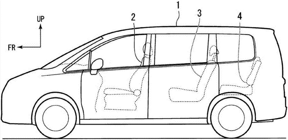
[0038] figure 1 It is a left side view of the vehicle 1 provided with the seat cover according to the embodiment.

[0039] Such as figure 1 As shown, a front seat 2 , a second seat 3 and a third seat 4 are provided on the floor of the interior of the vehicle 1 . The front seat 2, the second seat 3, and the third seat 4 are arranged at intervals from the front of th...


PUM


Abstract

The invention provides a seat cover and a vehicle. The seat cover (600) is arranged between a floor (5) and a seat (11) and comprises a first cover (61). The floor comprises a pair of sliding rails (20) used for supporting the seat (11) in a slidable manner. A connection part (50) used for connecting a floor wire harness (51) of the side of the floor (5) and a seat wire harness (52) of the side of the seat (11) covers one side of the first cover (61) from the length direction of the sliding rails (20). The connection of the connection part (50) is possible. Thus, according to the invention, the working efficiency for connecting the side of the floor and the side of the seat can be improved.

Description

technical field [0001] The present invention relates to a seat cover and a vehicle. Background technique [0002] Conventionally, there is known a wiring structure of a wire harness (Wire Harness) for wiring (cable installation) a slide seat. In this wiring structure, in order to supply power to electrical components mounted on the sliding seat, the floor wiring harness on the floor side and the seat wiring harness on the sliding seat side are electrically connected through connectors (for example, refer to Patent Literature 1). [0003] prior art literature [0004] patent documents [0005] [Patent Document 1] Japanese Invention Patent Laid-Open Publication No. 2015-97435 [0006] However, since the connecting work of the connector is performed while the sliding seat is lifted and tilted, there is a problem of improving work efficiency when connecting the floor side and the seat side. Contents of the invention [0007] In view of this, an object of the present inven...

Claims


Application Information

Patent Timeline
Patent Type & Authority Applications(China)
IPC IPC(8): B60N2/58B60N2/06B60R16/02
CPCB60N2/06B60N2/58B60R16/0215
Inventor 松本学湊宗笃
Owner HONDA MOTOR CO LTD
Why Eureka
Try Eureka