Device for temperature measurement and fault diagnosis of switch cabinet

A technology of fault diagnosis and temperature measurement, which is applied in the direction of measuring devices, applications of thermometers, and parts of thermometers, etc., which can solve the problems of complicated installation process and high cost of sensors

Inactive Publication Date: 2017-08-04
ZHONGSHAN POWER SUPPLY BUREAU OF GUANGDONG POWER GRID
7 Cites 0 Cited by

AI-Extracted Technical Summary

Problems solved by technology

[0004] The embodiment of the present invention provides a switchgear temperature measurement and fault diagnosis device, which solves the problem that the installation process of the existing ...

Abstract

The embodiment of the invention discloses a device for temperature measurement and fault diagnosis of a switch cabinet, and is used for solving the technical problems that the sensor installation process of an existing device for temperature measurement and fault diagnosis of a switch cabinet is complicated, power outage of a power supply system is needed to perform installation operation, all key electric contacts in the switch cabinet all need to be equipped with a temperature sensor, and the cost is high. The device for temperature measurement and fault diagnosis of the switch cabinet includes magnetic type wireless temperature sensors and a wireless receiving display terminal, wherein the magnetic type wireless temperature sensors are arranged outside a cabinet body of the switch cabinet, and are connected with the wireless receiving display terminal through wireless signals.

Application Domain

Thermometer detailsThermometer applications

Technology Topic

Temperature measurementEngineering +4

Image

  • Device for temperature measurement and fault diagnosis of switch cabinet
  • Device for temperature measurement and fault diagnosis of switch cabinet
  • Device for temperature measurement and fault diagnosis of switch cabinet

Examples

  • Experimental program(1)

Example Embodiment

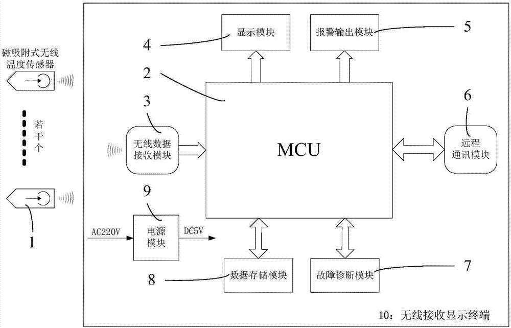
[0019] The embodiment of the present invention provides a switchgear temperature measurement and fault diagnosis device, which is used to solve the complicated sensor installation process of the existing switchgear temperature measurement and fault diagnosis device, and the installation and operation of the power supply system are required. A temperature sensor needs to be installed at the key electrical contacts, which is a technical problem with high cost.
[0020] In order to make the objectives, features, and advantages of the present invention more obvious and understandable, the technical solutions in the embodiments of the present invention will be described clearly and completely in conjunction with the accompanying drawings in the embodiments of the present invention. Obviously, the following The described embodiments are only a part of the embodiments of the present invention, rather than all the embodiments. Based on the embodiments of the present invention, all other embodiments obtained by those of ordinary skill in the art without creative work shall fall within the protection scope of the present invention.
[0021] See figure 1 An embodiment of a switchgear temperature measurement and fault diagnosis device provided in the embodiment of the present invention includes:
[0022] A magnetic wireless temperature sensor 1, a wireless receiving and display terminal 10, the magnetic wireless temperature sensor 1 is arranged outside the switch cabinet; the magnetic wireless temperature sensor 1 is connected to the wireless receiving and display terminal through a wireless signal 10.
[0023] Further, the wireless receiving and displaying terminal 10 includes a wireless data receiving module 3, and the wireless data receiving module 3 and the magnetic wireless temperature sensor 1 are connected by wireless signals.
[0024] Further, the wireless receiving and display terminal 10 further includes: an MCU2 and a display module 4, and the MCU2 is connected to the display module 4 and the wireless data receiving module 3.
[0025] Further, the wireless receiving and displaying terminal 10 further includes: an alarm output module 5, and the MCU2 is connected to the alarm output module 5.
[0026] Further, the wireless receiving and displaying terminal 10 further includes a remote communication module 6, and the MCU 2 is connected to the remote communication module 6.
[0027] Further, the wireless receiving and display terminal 10 further includes: a fault diagnosis module 7, and the MCU 2 is connected to the fault diagnosis module 7.
[0028] Further, the wireless receiving and display terminal 10 further includes a data storage module 8, and the MCU 2 is connected to the data storage module 8.
[0029] Further, there is at least one magnetic-attracted wireless temperature sensor 1.
[0030] Further, the wireless receiving and display terminal 10 further includes: a power supply module 9 connected to the magnetic wireless temperature sensor 1 and the MCU 2.
[0031] Further, the wireless data receiving module 3 is used to receive the wireless temperature measurement data of the magnetic wireless temperature sensor 1; the fault diagnosis module 7 is used to check the temperature measurement data through a built-in temperature measurement fault diagnosis algorithm. The temperature data and diagnostic parameters are calculated and the diagnostic calculation result is output; the MCU2 is used to manage and control the wireless data receiving module 3, the display module 4, the alarm output module 5, the remote communication module 6, The data storage module 8 and the fault diagnosis module 7.
[0032] Normal switchgear temperature measurement uses direct temperature measurement. The temperature sensor directly measures the electrical contacts of the primary equipment. In this embodiment, through indirect temperature measurement of the switchgear, the temperature sensor does not need to be installed inside the switchgear. On the conductor, it is installed in the switch cabinet shell and the secondary instrument room away from the primary conductor, which can ensure the convenience and safety of the installation process, and solve the complex sensor installation process of the existing switch cabinet temperature measurement and fault diagnosis device. The power supply system needs to be powered off to install and operate. All key electrical contacts in the switch cabinet need to be installed with a temperature sensor, which is a technical problem with high cost.
[0033] Such as figure 1 A device for temperature measurement and fault diagnosis of a switch cabinet provided in this embodiment includes: a magnetically attracted wireless temperature sensor 1, a wireless receiving and display terminal 10.
[0034] The magnetic wireless temperature sensor 1 is arranged on the top of the switchgear cabinet or the heat sensitive point of the secondary instrument room, and is connected to the wireless receiving and displaying terminal 10 through wireless transmission.
[0035] The wireless receiving and display terminal 10 is composed of MCU2, wireless data receiving module 3, display module 4, alarm output module 5, remote communication module 6, fault diagnosis module 7, data storage module 8, power supply module 9 and other modules. Each sub-module is managed and controlled by MCU2.
[0036] The wireless data receiving module 3 is responsible for receiving wireless temperature measurement data from front-end sensors;
[0037] The display module 4 is used to display temperature measurement data and calculation result data, and can indicate the operating status of the equipment;
[0038] The alarm output module 5 is used for output control of alarm signals;
[0039] The remote communication module 6, when needed, can communicate with the background management system, transmit all monitoring data and diagnosis result data, and can transmit configuration information and control commands of the background system to the wireless reception display terminal 10;
[0040] The fault diagnosis module 7 is responsible for comprehensively calculating the temperature measurement data and diagnosis parameters according to the built-in indirect temperature measurement fault diagnosis algorithm, and outputting the diagnosis calculation result;
[0041] The data storage module 8 is responsible for storing temperature data, calculation processes and storage of result data;
[0042] Taking the static diagnosis algorithm of a thermal physical model of a high-voltage switchgear as an example, the calculation method of the high-voltage switchgear overheating early warning and fault alarm triggering threshold through the indirect point temperature is explained in detail:
[0043] The static heat balance relationship between the temperature of the indirect temperature measurement point and the temperature of the primary heat source and the temperature of the environmental reference point
[0044]
[0045] θ 0 Is the static temperature of the environmental reference point, usually -20℃≤θ e (t)≤50℃.
[0046] θ 1 Is the static temperature of the lumped heat source of the circuit breaker.
[0047] θ 2 It is the static temperature of the indirect temperature measurement point of the high-voltage cabinet.
[0048] k 2 Is the characteristic temperature rise state coefficient of the indirect temperature measurement point of the high-voltage switchgear,
[0049]
[0050] k 2 The value does not change much within a certain temperature range and load range. In the general diagnosis calculation process, it is taken as the normal system. Fitting results according to experimental data: 1250A high voltage switchgear, k 2 ≈0.286, 3150A high voltage switch cabinet, k 2 ≈0.446. According to the above formula, the alarm threshold of the indirect temperature measurement point can be calculated according to the alarm threshold of the primary equipment and the current ambient temperature.
[0051] In this embodiment, through the magnetic wireless temperature sensor 1, the wireless receiving and display terminal 10, the magnetic wireless temperature sensor 1 is set on the top of the switchgear cabinet or the thermally sensitive point of the secondary instrument room, and uses wireless transmission. Connected to the wireless receiving display terminal 10, the wireless receiving display terminal 10 includes the MCU2, the wireless data receiving module 3, the display module 4, the alarm output module 5, the remote communication module 6, the fault diagnosis module 7, the data storage module 8, and the power supply module 9. The various functions of temperature data wireless reception, storage, calculation and fault diagnosis are integrated in a terminal. The whole set of equipment has simple structure, high monitoring efficiency and accurate diagnosis results. The magnetic wireless temperature sensor 1 can be installed flexibly and quickly, and is suitable for various This kind of power engineering renovation project provides a low-cost and fast solution for the intelligent transformation of old power equipment in the field of power switchgear temperature measurement fault diagnosis, which solves the existing switchgear temperature measurement and fault diagnosis. The installation process of the device sensor is complicated, and the power supply system needs to be powered off to install and operate. All key electrical contacts in the switch cabinet need to install a temperature sensor, which is a technical problem with high cost.
[0052] Those skilled in the art can clearly understand that, for the convenience and conciseness of the description, the specific working process of the system, device and unit described above can refer to the corresponding process in the foregoing method embodiment, which will not be repeated here.
[0053] In the several embodiments provided in this application, it should be understood that the disclosed system, device, and method may be implemented in other ways. For example, the device embodiments described above are merely illustrative. For example, the division of the units is only a logical function division, and there may be other divisions in actual implementation, for example, multiple units or components may be combined or It can be integrated into another system, or some features can be ignored or not implemented. In addition, the displayed or discussed mutual coupling or direct coupling or communication connection may be indirect coupling or communication connection through some interfaces, devices or units, and may be in electrical, mechanical or other forms.
[0054] The units described as separate components may or may not be physically separated, and the components displayed as units may or may not be physical units, that is, they may be located in one place, or they may be distributed on multiple network units. Some or all of the units may be selected according to actual needs to achieve the objectives of the solutions of the embodiments.
[0055] In addition, the functional units in each embodiment of the present invention may be integrated into one processing unit, or each unit may exist alone physically, or two or more units may be integrated into one unit. The above-mentioned integrated unit can be implemented in the form of hardware or software functional unit.
[0056] If the integrated unit is implemented in the form of a software functional unit and sold or used as an independent product, it can be stored in a computer readable storage medium. Based on this understanding, the technical solution of the present invention essentially or the part that contributes to the prior art or all or part of the technical solution can be embodied in the form of a software product, and the computer software product is stored in a storage medium , Including several instructions to make a computer device (which may be a personal computer, a server, or a network device, etc.) execute all or part of the steps of the method described in each embodiment of the present invention. The aforementioned storage media include: U disk, mobile hard disk, read-only memory (ROM, Read-Only Memory), random access memory (RAM, Random Access Memory), magnetic disks or optical disks and other media that can store program codes.
[0057] As mentioned above, the above embodiments are only used to illustrate the technical solutions of the present invention, but not to limit them; although the present invention has been described in detail with reference to the foregoing embodiments, those of ordinary skill in the art should understand that: The technical solutions recorded in the embodiments are modified, or some of the technical features are equivalently replaced; these modifications or replacements do not cause the essence of the corresponding technical solutions to deviate from the spirit and scope of the technical solutions of the embodiments of the present invention.

PUM

no PUM

Description & Claims & Application Information

We can also present the details of the Description, Claims and Application information to help users get a comprehensive understanding of the technical details of the patent, such as background art, summary of invention, brief description of drawings, description of embodiments, and other original content. On the other hand, users can also determine the specific scope of protection of the technology through the list of claims; as well as understand the changes in the life cycle of the technology with the presentation of the patent timeline. Login to view more.
Why Eureka
Try Eureka