Self-locking bracket and opening method thereof

A technology of self-locking brackets and brackets, which is applied in the field of orthodontic equipment, can solve problems such as the complexity of orthodontic work, reduce the bonding force of self-locking brackets, and increase the working hours of doctors, so as to achieve convenient orthodontic work, Guarantee the effect of correction and reduce the effect of working hours

Pending Publication Date: 2017-08-08
GUANGZHOU OO MEDICAL SCI LTD
View PDF5 Cites 9 Cited by
  • Summary
  • Abstract
  • Description
  • Claims
  • Application Information

AI Technical Summary

Problems solved by technology

[0004] In order to facilitate the opening of the arch wire slot on the bracket main body, an opening position is usually set on the bracket main body. However, the setting of the opening position does not bring convenience for the doctor to open the arch wire slot. When the doctor opens the arch wire slot, usually The following two methods: 1. The opening of the arch wire slot is realized by using an external special tool, which brings great inconvenience to the doctor’s orthodontic work, complicates the doctor’s orthodontic work, and increases the 2. Apply a force parallel to the arch wire slot to the probe to make the cover slide. This method will form static friction between the self-ligating bracket and the tooth surface, thereby reducing the adhesion of the self-ligating bracket. The joint force will affect the effect of orthodontic treatment, prolong the period of orthodontic treatment, and with the increase of time, self-ligating brackets will easily fall off, causing medical accidents

Method used


Image

  • Self-locking bracket and opening method thereof
  • Self-locking bracket and opening method thereof
  • Self-locking bracket and opening method thereof

Examples


Embodiment 1

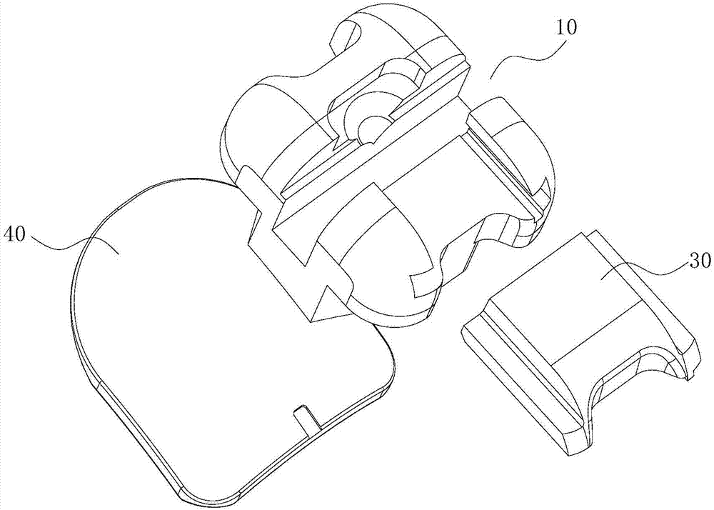
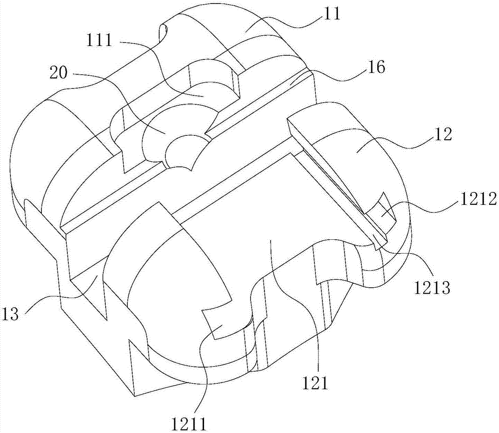
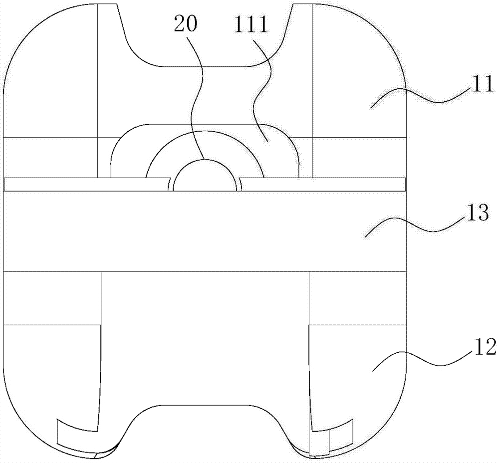
[0058] Such as Figure 1 to Figure 5 As shown, the self-ligating bracket includes a bracket main body 10 and a cover body 30. The bracket main body 10 has a first bracket wing 11 and a second bracket wing 12. The bracket main body 10 is provided with an arch wire groove 13. The thread groove 13 is arranged between the first bracket wing 11 and the second bracket wing 12, and runs through the bracket main body 10;

[0059] The cover body 30 is arranged on the second bracket wing 12 and movably cooperates with the second bracket wing 12 , the cover body 30 is used to open or close the archwire slot 13 ;

[0060] An opening slope 20 is provided on at least one of the first bracket wing 11 and the cover body 30 , and the opening slope 20 is provided at the inner end of the first bracket wing 11 or the cover body 30 and is close to the archwire slot 13 ;

[0061] The archwire slot 13 and the first bracket wing 11 form a first side 14, the archwire slot 13 and the second bracket wi...

Embodiment 2

[0086] Such as Figure 6 and Figure 7 As shown, the difference between this embodiment and Embodiment 1 is:

[0087] The opening slope 20 is arranged on the first bracket wing 11, and the top of the opening slope 20 is in contact with the top of the first bracket wing 11. The opening slope 20 is a curved slope, and the opening slope 20 has a first side and a second side. Two side portions, the top of the opening slope 20 is arc-shaped, the top of the opening slope 20 smoothly transitions to the bottom of the opening slope 20 along the first side and the second side, and the top of the opening slope 20 moves toward its bottom The opening slope 20 gradually becomes smaller, and the bottom of the opening slope 20 is arc-shaped or pointed. In this embodiment, the bottom of the opening slope 20 is a point.

[0088] The advantage of this embodiment:

[0089]The opening slope 20 is a curved slope, and the shape of the opening slope 20 can match the shape of many tools, which can ...

Embodiment 3

[0092] Such as Figure 8 As shown, the difference between this embodiment and Embodiment 1 is:

[0093] The first bracket wing 11 is provided with a sunken opening position 111, the opening position 111 is set at the inner end of the first bracket wing 11, and is close to the arch wire groove 13; the opening slope 20 is set at the bottom end surface of the opening position 111 , and the top of the opening slope 20 is in contact with the bottom end surface of the opening position 111;

[0094] In this embodiment, the bottom end surface of the opening position 111 is an inclined surface, and the inclined surface is an opening inclined surface 20. The opening inclined surface 20 is a straight inclined surface. The opening inclined surface 20 has a first side portion and a second side portion. The top smoothly transitions to the bottom of the opening slope 20 along the first side and the second side; the bottom of the opening slope 20 is in contact with the receiving step 16 .

...


PUM


Abstract

The invention discloses a self-locking bracket and an opening method thereof. The self-locking bracket comprises a bracket main body and a cover body, wherein the bracket main body is provided with a first bracket wing and a second bracket wing; an arch wire slot is formed in the bracket main body; the arch wire slot is formed between the first bracket wing and the second bracket wing; the cover body is arranged on the second bracket wing and is movably matched with the second bracket wing; an opening slope is arranged on at least one of the first bracket wing and the cover body; the opening slope is arranged at the end part of the inner side of the first bracket wing or the cover body and is close to the arch wire slot. The self-locking bracket opening method comprises the following steps: placing the end part of an opening tool on the opening slope, and enabling the end part of the opening tool to slide along the opening slope, to push the cover body to slide along the sliding direction. According to the self-locking bracket and the opening method thereof, a doctor can conveniently open the arch wire slot, and convenience is brought to tooth correction work of the doctor.

Description

technical field [0001] The invention relates to the field of orthodontic appliances, in particular to a self-locking bracket and an opening method thereof. Background technique [0002] Brackets are an important part of fixed orthodontic technology. Arch wires exert various types of orthodontic force on teeth through brackets. The main function of brackets is to fix arch wires, so that arch wires can play a better role and transmit orthodontic forces. , so as to control the three-dimensional movement of teeth to achieve the purpose of orthodontic treatment. [0003] Most of the existing self-locking brackets include a bracket main body and a cover body, and the cover body is slidably connected to the bracket main body for opening or closing the archwire slot of the bracket main body. [0004] In order to facilitate the opening of the arch wire slot on the bracket main body, an opening position is usually set on the bracket main body. However, the setting of the opening posi...

Claims


Application Information

Patent Timeline
Patent Type & Authority Applications(China)
IPC IPC(8): A61C7/34
CPCA61C7/34A61C2204/00A61C7/287A61C7/02
Inventor 吉利
Owner GUANGZHOU OO MEDICAL SCI LTD
Why Eureka
Try Eureka