Eureka AIR delivers breakthrough ideas for toughest innovation challenges, trusted by R&D personnel around the world.

Decorative coating device

A decorative coating and sliding technology, applied in mixers with rotary stirring devices, transportation, packaging, dissolving, etc., can solve the problems of uneven stirring, easy splashing, complicated operation, etc., to improve stirring efficiency and prevent movement. Overtravel, simple operation effect

Inactive Publication Date: 2017-08-08
QUAZHOU GANGSHENGLILAI IMPORT & EXPORT TRADE CO LTD
View PDF0 Cites 14 Cited by
  • Summary
  • Abstract
  • Description
  • Claims
  • Application Information

AI Technical Summary

Problems solved by technology

[0002] Paint is the most common raw material for painting in modern home decoration. It is mostly in powder form and needs to be mixed with water before use. In traditional technology, the stirring of paint before use is generally done by manual stirring, which has low stirring efficiency. Stirring is relatively uneven, leaving more powder lumps, affecting the painting effect, and it is easy to splash and cause waste. At the same time, it is difficult to ensure the cleanliness of the surrounding facilities. , the operation is cumbersome and the size is too large to meet the needs of interior decoration

Method used


Image

  • Decorative coating device
  • Decorative coating device
  • Decorative coating device

Examples


Embodiment Construction

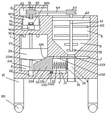
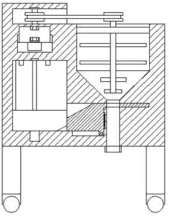
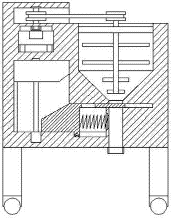
[0023] Such as Figure 1-Figure 5 As shown, a decorative coating device of the present invention includes a substrate 1, a first sliding joint cavity 2 is provided inside the left side of the substrate 1, and a first guide groove 23 is provided on the left inner wall of the first sliding joint cavity 2, The base body 1 on the right side of the first sliding joint cavity 2 is provided with a second sliding joint cavity 3 communicating with the first sliding joint cavity 2, and the base body 1 on the right side of the second sliding joint cavity 3 is provided with The output slot 4 is elongated up and down. The top of the second sliding joint chamber 3 is provided with a closed slot 7 that passes through the output slot 4 and extends to the right. The top of the output slot 4 is provided with a bucket-shaped part 5. The top of the bucket-shaped part 5 is provided with a stirring part 6, and the base 1 above the first sliding joint cavity 2 is provided with a third sliding joint ...


PUM


Abstract

The invention discloses a decorative coating device. The decorative coating device comprises a base body, wherein the interior of the left side of the base body is provided with a first sliding connection cavity; the inner wall of the left side of the first sliding connection cavity is provided with a first guide groove; the interior of the base body at the right side of the first sliding connection cavity is provided with a second sliding connection cavity which is communicated with the first sliding connection cavity; the interior of the base body at the right side of the second sliding connection cavity is provided with an output groove which can extend up and down; the top part of the second sliding connection cavity is provided with a sealing groove which penetrates through the output groove and extends to the right side; a hopper-shaped part is arranged at the top part of the output groove, and a uniform stirring part is arranged at the top part of the hopper-shaped part; the interior of the base body above the first sliding connection cavity is provided with a third sliding connection cavity; the inner walls of left side and right side of the third sliding connection cavity are correspondingly provided with third guide grooves; a spiral rod is arranged in the first sliding connection cavity, the bottom part of the spiral rod is connected with a first electric rotation machine, and the spiral rod is in matched connection with a push-up block by threads. The decorative coating device has the advantages that the structure is simple, the design is reasonable, and the operation is simple; the stirring and material discharging are automatically controlled, the labor intensity of workers is decreased, the use cost is lower, the stirring is more uniform, the stirring efficiency is improved, and the existing requirements are met.

Description

technical field [0001] The invention relates to the technical field of interior decoration equipment, in particular to a decorative coating device. Background technique [0002] Paint is the most common raw material for painting in modern home decoration. It is mostly in powder form and needs to be mixed with water before use. In traditional technology, the stirring of paint before use is generally done by manual stirring, which has low stirring efficiency. Stirring is relatively uneven, leaving more powder lumps, affecting the painting effect, and it is easy to splash and cause waste. At the same time, it is difficult to ensure the cleanliness of the surrounding facilities. , the operation is cumbersome and the size is too large to meet the needs of interior decoration. Contents of the invention [0003] The technical problem to be solved by the present invention is to provide a decorative paint device, which can solve the above-mentioned problems in the prior art. [0...

Claims


Application Information

Patent Timeline
IPC IPC(8): B01F7/18B01F15/02
CPCB01F27/90B01F35/75471B01F2101/30
Inventor 张雨晴
Owner QUAZHOU GANGSHENGLILAI IMPORT & EXPORT TRADE CO LTD
Why Eureka
Eureka Blog
Learn More