
Component clamping device

A clamping device and component clamping technology, applied in vices, manufacturing tools, etc., can solve the problems of reduced processing efficiency and long time, and achieve the effects of improving processing efficiency, low manufacturing cost, and preventing falling off

Inactive Publication Date: 2017-08-08
XIAN AIRCRAFT DESIGN INST OF AVIATION IND OF CHINA
View PDF0 Cites 3 Cited by
  • Summary
  • Abstract
  • Description
  • Claims
  • Application Information

AI Technical Summary

Problems solved by technology

However, because the pitch of the tightening bolts of the clamp or open vise is very small, it takes a long time to open the jaws a certain distance, and it takes a long time to close when re-clamping, which reduces the processing time. efficiency

Method used


Image

  • Component clamping device
  • Component clamping device
  • Component clamping device

Examples


specific Embodiment

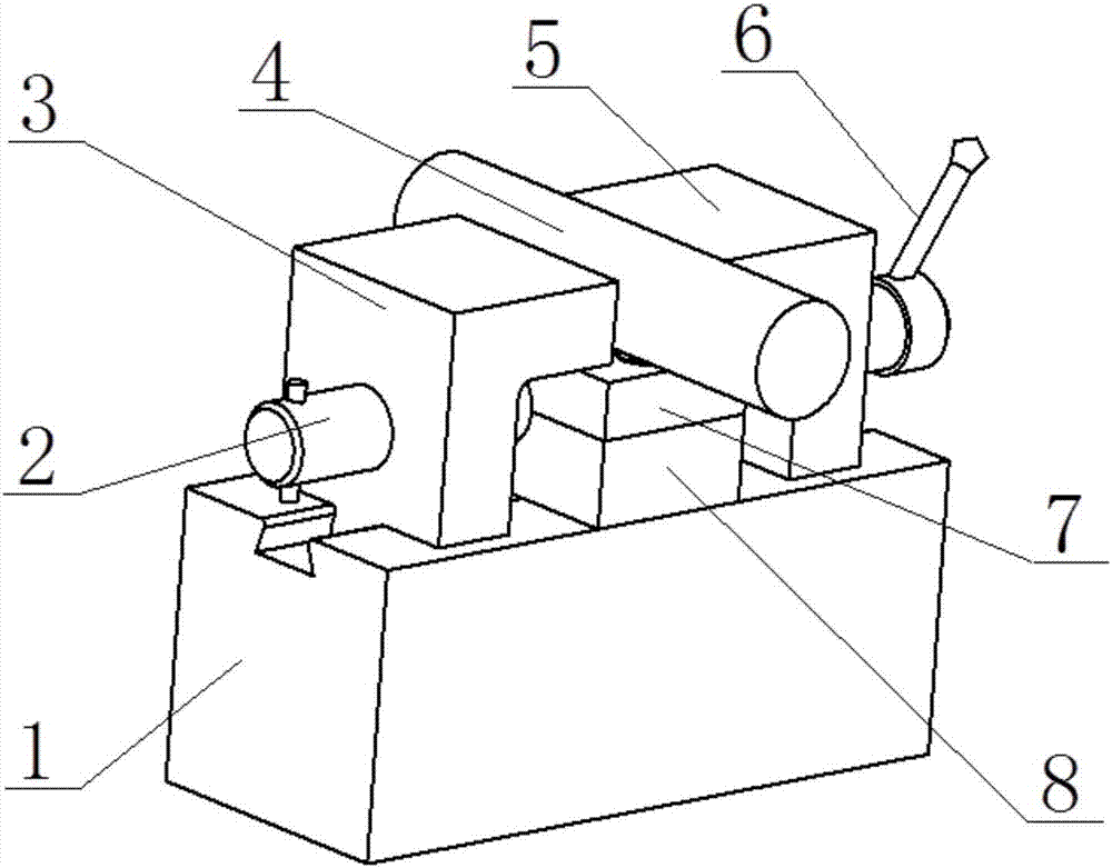
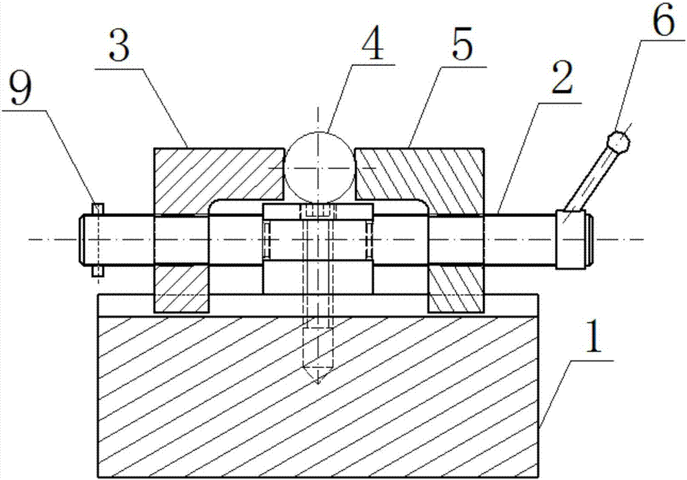
[0030] One of the embodiments of the mounting member clamping device is as follows: first place the lower clamp block 8 on the upper surface of the base 1, then place the middle part of the threaded rod 2 on the lower clamp block 8, and then place the upper clamp block 7 is placed on the lower clamp block 8. At this time, the threaded rod 2 is clamped between the upper clamp block 7 and the lower clamp block 8, and because the diameter of the middle part is smaller than that of the two ends, the diameter of the threaded rod 2 is limited. Move axially; then insert the left clamping block 3 and the right clamping block 5 into the two ends of the threaded rod 2 respectively, at this time the T-shaped grooves at the bottom of the left clamping block 3 and the right clamping block 5 all enter the base 1 In the T-shaped boss 10 in the middle; finally, the handle 6 and the pin 9 are installed on the two ends of the threaded rod 2 respectively.

[0031] When using the component clampi...


PUM


Abstract

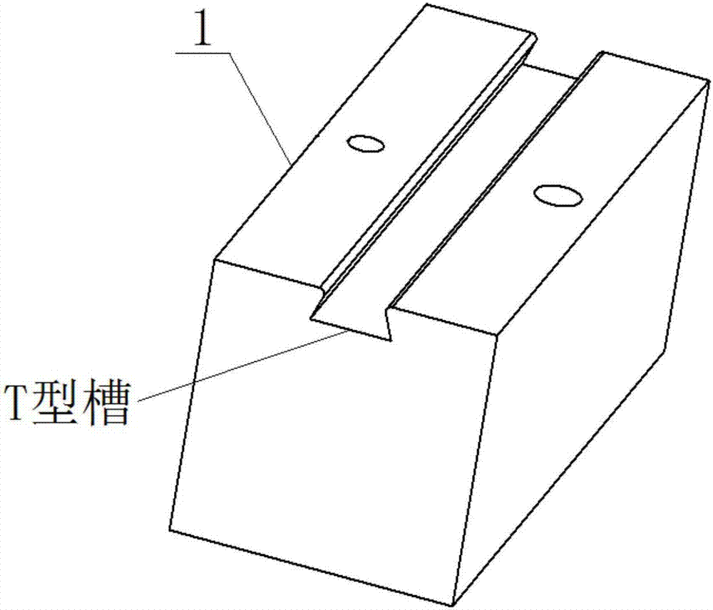
A component clamping device provided by the present invention includes a base, a clamping structure and a clamping structure, a T-shaped groove is opened on the surface of the base, the clamping structure includes an upper clamping block and a lower clamping block, and the middle part is fixed on The threaded rod between the upper clamp block and the lower clamp block, the upper clamp block and the lower clamp block are fixed on the base, and the two ends of the threaded rod are respectively provided with left-handed threads and right-handed threads; the clamping structure includes left-handed The clamping block and the right clamping block, the left clamping block is provided with threads matching the thread rotation direction of one end of the threaded rod, the right clamping block is provided with threads matching the thread rotation direction of the other end of the threaded rod, the left Both the clamping block and the right clamping block are connected to the threaded rod through threads, and the bottoms of the left clamping block and the right clamping block are provided with T-shaped bosses matching the T-shaped slots of the base. The component clamping device improves processing efficiency, increases device stability, has simple structure and low manufacturing cost.

Description

technical field [0001] The invention relates to the technical field of component clamps, in particular to a component clamping device. Background technique [0002] At present, when parts need to be clamped, clamps or open vises are generally used to clamp the components. When the clamps or open vises are released to remove components, some components cannot Axial extraction can only be taken out radially upwards, which requires that the jaws must be opened a certain distance to take out the component. However, because the pitch of the tightening bolts of the clamp or open vise is very small, it takes a long time to open the jaws a certain distance, and it takes a long time to close when re-clamping, which reduces the processing time. efficiency. Contents of the invention [0003] In order to overcome the above-mentioned defects in the prior art, the present invention provides a component clamping device, which includes a base, a hoop structure and a clamping structure. ...

Claims


Application Information

Patent Timeline
Patent Type & Authority Applications(China)
IPC IPC(8): B25B1/10B25B1/02B25B1/24
CPCB25B1/10B25B1/02B25B1/24
Inventor 曲春远路航吴平军王卓
Owner XIAN AIRCRAFT DESIGN INST OF AVIATION IND OF CHINA
Learn More