Check patentability & draft patents in minutes with Patsnap Eureka AI!

Cast-in-place method of comprehensive pipe gallery

A comprehensive pipe gallery and cast-in-place technology, which is applied in water conservancy projects, artificial islands, underwater structures, etc., can solve the problems of low cast-in-place efficiency and achieve high efficiency

Inactive Publication Date: 2017-08-08
贾登忠
View PDF8 Cites 6 Cited by
  • Summary
  • Abstract
  • Description
  • Claims
  • Application Information

AI Technical Summary

Problems solved by technology

[0003] The pouring method of the comprehensive pipe gallery generally adopts the prefabrication method or the cast-in-place method, but the traditional cast-in-place method is the method of manually nailing the formwork, and its cast-in-place efficiency is relatively low

Method used


Image

  • Cast-in-place method of comprehensive pipe gallery
  • Cast-in-place method of comprehensive pipe gallery
  • Cast-in-place method of comprehensive pipe gallery

Examples


Embodiment Construction

[0023] The present invention will be further described below in conjunction with the accompanying drawings.

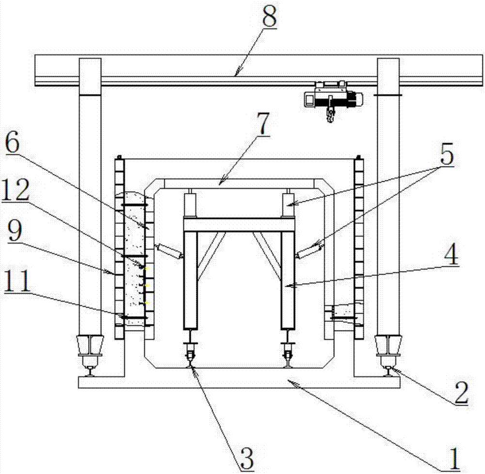
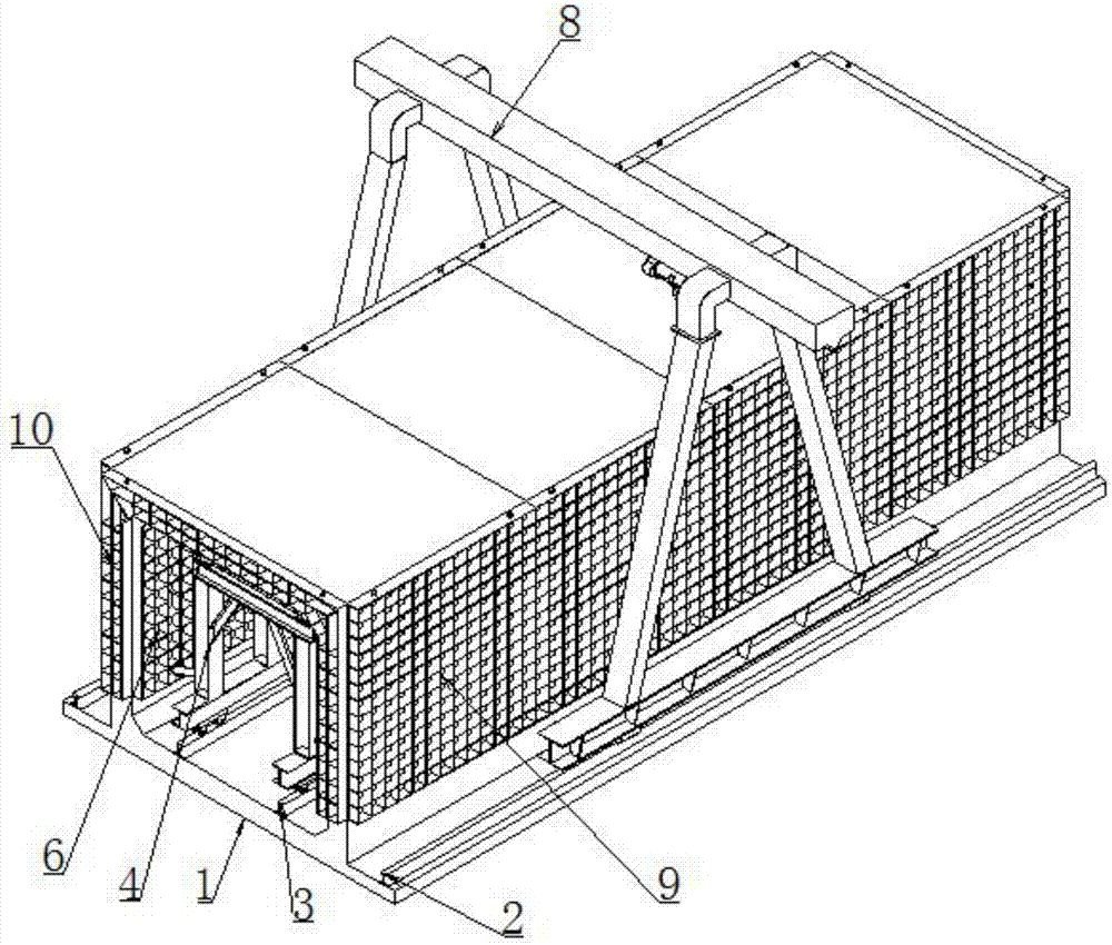
[0024] Such as figure 1 , figure 2 and image 3 As shown, a cast-in-place method for a comprehensive pipe gallery includes the following steps:

[0025] 1) Geotechnical excavation of the pipe gallery channel and pouring of the foundation pedestal 1; and pouring the bottom corners on both sides of the pipe gallery on the foundation pedestal 1;

[0026] 2) Build mobile spreader tracks 2 on both sides of the foundation pedestal 1, and build trolley tracks 3 in the middle;

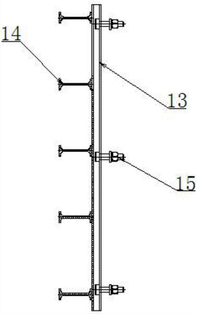
[0027] 3) Use the mobile trolley 4 on the trolley track 3 to support the inner mold of the pipe gallery: a hydraulic cylinder 5 is arranged above the trolley 4, and is connected to the inner upper mold 7 of the inner mold; hydraulic pressure cylinders are also installed on both sides of the trolley 4 Cylinder 5 is connected with both sides inner mold 6 of inner mold respectively; The outer side of...


PUM


Abstract

The invention discloses a cast-in-place method of a comprehensive pipe gallery. The cast-in-place method comprises the steps that 1), a basic table pedestal is cast; 2), a sling rail and a trolley rail are built; 3), a movable trolley is used for jacking a pipe gallery internal mold; 4), a movable sling is used for erecting an external mold and a mouth mold, and the external mold and the internal mold are fixedly connected with the mouth mold in an edge-to-edge manner; 5), a reinforcement cage is hoisted into the molds; 6), the external mold and the internal mold are tensioned and connected, and a cast-in-place frame mold is formed; 7), concrete casting is carried out; and 8), the pipe gallery is formed, the external mold, the internal mold and the mouth mold are detached, and the internal upper mold and the inner side faces on the two sides are contracted inwards through a hydraulic cylinder of the trolley, and in-place casting of a next pipe gallery continues to be carried out according to the steps 1-6. Fast mounting of the pipe gallery molds is achieved through the trolley and the sling, and casting is convenient.

Description

technical field [0001] The invention relates to the technical field of a comprehensive pipe gallery used in urban underground pipe network systems, in particular to an in-situ casting method for a comprehensive pipe gallery. Background technique [0002] The comprehensive pipe corridor refers to the construction of a municipal shared underground tunnel under the urban road, which integrates various municipal pipelines such as electricity, communication, water supply, and gas, and implements "unified planning, unified construction, and unified management" to achieve underground space. Comprehensive utilization and resource sharing. [0003] The pouring method of the comprehensive pipe gallery generally adopts the prefabrication method or the cast-in-place method, but the traditional cast-in-place method is the method of manually nailing the formwork, and its cast-in-place efficiency is relatively low. Contents of the invention [0004] The object of the present invention i...

Claims


Application Information

Patent Timeline
IPC IPC(8): E02D29/045
CPCE02D29/045E02D29/10
Inventor 贾登忠
Owner 贾登忠
Features
  • R&D
  • Intellectual Property
  • Life Sciences
  • Materials
  • Tech Scout
  • Unparalleled Data Quality
  • Higher Quality Content
  • 60% Fewer Hallucinations
Learn More