
Test device and test method for simulating soil arching effect

A technology for simulating test and soil arching effect, applied in soil material testing, material inspection products, etc., can solve problems such as inability to study soil arching effect, failure to study pipe culvert or box culvert soil arching effect, lack of soil arching effect test equipment, etc.

Active Publication Date: 2017-08-08
安徽中意之旅信息科技有限公司
View PDF7 Cites 10 Cited by
  • Summary
  • Abstract
  • Description
  • Claims
  • Application Information

AI Technical Summary

Problems solved by technology

The idea of ​​the above literature is good, but it cannot study the soil arch effect of pipe culvert or box culvert
In addition, the displacement of soil between piles is not the same at different pile numbers. The above two documents did not consider the above factors when conducting tests, so the soil arching effect under different displacements of soil between piles cannot be studied.
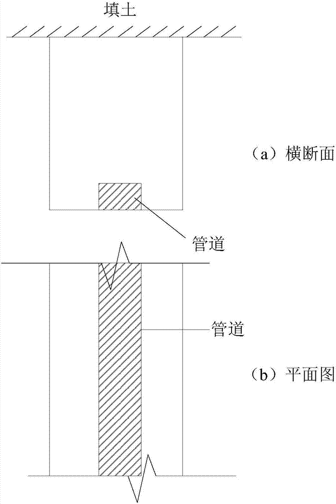
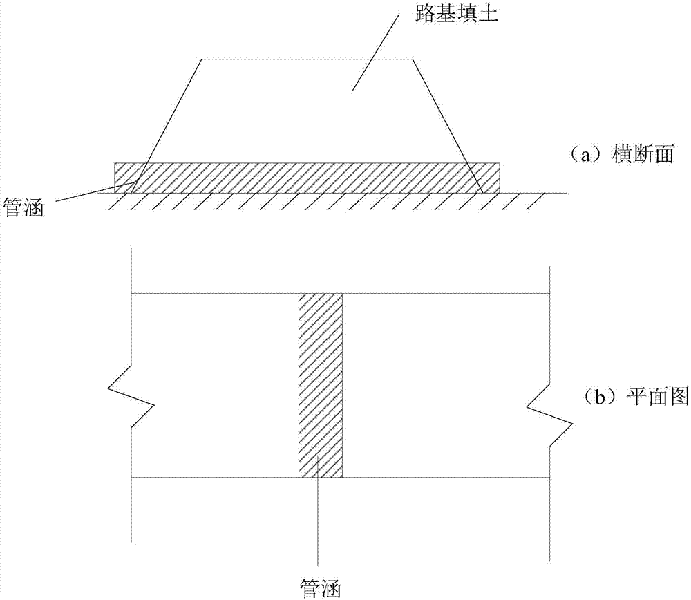
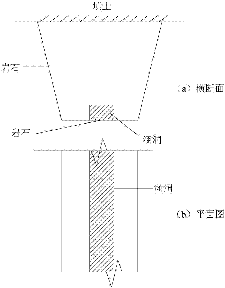
[0007] The actual working conditions of different projects are varied, such as figure 1 Pipeline backfill under plane strain conditions shown, figure 2 The subgrade pipe and culvert filling shown, image 3 The trapezoidal valley box culvert shown in the backfill, Figure 4 The above-mentioned actual engineering problem is generally that the vertical displacement of the pipe / pipe culvert / box culvert is relatively large compared with the surrounding soil due to its heavy weight (active arch effect) ), but when the pipe / pipe culvert / box culvert adopts pile foundation, the displacement of the structure in this case is smaller than that of the surrounding soil, and the similar simulation test of the soil arch effect in this case has not been carried out enough Research on (Passive Arch Effect Caused by Pipe Culverts)
In addition, the displacement of structures has a large spatial effect, but there is no literature report to conduct experimental research on this problem
[0008] To sum up, the existing test settings are mainly set up for a certain type of engineering situation. When studying another engineering situation, it is necessary to redesign the test instruments, and there is a lack of relatively general soil arch effect test instruments.

Method used


Image

  • Test device and test method for simulating soil arching effect
  • Test device and test method for simulating soil arching effect
  • Test device and test method for simulating soil arching effect

Examples


Embodiment 1

[0056] Example 1: Simulation of soil deformation of subgrade pipe culvert filling: pipe culvert / box culvert is perpendicular to the subgrade, and its foundation adopts cushion foundation;

[0057] As attached Figure 5-11 As shown, the soil arching effect simulation test device includes: a frame, a test box 4, and a lifting device 6;

[0058] Among them, the frame includes two upper beams 1-1, two lower beams 1-4, two platform beams 1-2, four columns 2, 6 longitudinal beams 1-3, platform beams 1-4 and longitudinal beam 1 -3 is provided with a load-bearing platform 3, and the test box 4 is fixed on the load-bearing platform 3; two longitudinal beams 1-3 are set at the positions of the upper beam 1-1 and the lower beam 1-4 to form a frame frame;

[0059] The test box 4 is composed of the main frame 4-1 of the box body and the surrounding plexiglass 4-2. The main frame 4-1 includes the upper beam, the lower beam and four columns. The lower beam and the four columns are provided with gla...

Embodiment 2

[0075] Embodiment two, combined with Figure 12-13 In the first embodiment, because there is a transverse keel below the settlement unit plate 5-4, the vertical displacement can only reach the height of the settlement unit plate higher than the non-settlement unit plate (equivalent to the height of the culvert higher than the original ground fill), Therefore, the first embodiment cannot simulate the situation where the culvert is located below the original ground height, which is equivalent to the situation where the surface of the settlement unit plate 5-4 is lower than the non-settlement unit plate 6-3.

[0076] Attached Picture 12 It can be seen that the settlement unit plate 5-4 is an integral plate. Compared with the original embodiment 1, the transverse keel under the settlement unit plate 5-4 is eliminated; this setting method can simulate the settlement of the settlement unit plate when it undergoes greater settlement deformation. Soil arching effect.

[0077] In order to ...

Embodiment 3

[0078] Embodiment 3: Combination Figure 14-16 Understand, single pipe culvert simulation under plane strain conditions: as attached Figure 14 As shown, the diameter of the pipe culvert is 1m, the total width of the backfilled soil is 2m, and the backfill height is 2m. According to the simulation of the ratio of 1:2, the settlement unit plate 5-4 is set in the middle with a width of 0.5m. Set a 0.25m non-settlement unit plate on each side, the length of the settlement unit plate and the non-settlement unit plate are both 2m and both are integral plates, and the non-settlement unit plate is directly fixed on the side wall of the box by screws or other methods;

[0079] By the attachment Figure 15-16 It can be seen that a row of jacking pipes 6-3 is uniformly distributed along the settling unit plate, the number of jacking pipes is 4, and the distance between the jacking pipes is 0.5m;

[0080] The cross-sectional graphics of the settlement unit plate 5-4 are: the upper semicircle a...


PUM


Abstract

The invention relates to a test device for simulating a soil arching effect. The test device comprises a test box and a lifting device, wherein a settling unit plate and nonsettling unit plates are arranged at the bottom of the test box; the lifting device comprises a rising and falling power device, a jacking tube platform plate and a jacking tube; the jacking tube platform plate rises or falls by the rising and falling power device; the jacking tube is used for rising and falling of the settling unit plate. Compared with the prior art, the test device has the advantages that the soil arching effect of backfill of works under a variety of working conditions can be simulated, and the soil arching effect of foundations of works in case of large deformation can be simulated.

Description

Technical field [0001] The invention relates to the field of geotechnical engineering test devices, in particular to a universal soil arching effect simulation test device and a use method thereof. Background technique [0002] The study of soil arching effect has been a hot topic in recent years. It plays an important role in many fields such as retaining walls, roadbeds, pipe culverts, tunnels, etc. The theory of soil arching effect has also been developed. [0003] In the study of soil arching effect, since Marston proposed the first in 1913 to create the theory of culvert soil pressure calculation, the procedures for establishing soil arching effect theory are basically the same: such as "Research on the Theory of Vertical Earth Pressure of Reinforced Concrete Box Culvert-Trapezoidal Valley Culvert (Chen Baoguo et al., Rock and Soil Mechanics)", "Research on Active Earth Pressure of Cohesive Fill Retaining Wall Considering Soil Arching Effect (Tu Bingxiong et al., Chinese Journ...

Claims


Application Information

Patent Timeline
IPC IPC(8): G01N33/24
Inventor 刘华
Owner 安徽中意之旅信息科技有限公司
Learn More