
Soil arching test box and method

A test box and soil arch technology, applied in the direction of applying stable tension/pressure to test the strength of materials, measuring devices, instruments, etc., can solve the problems of complex structure, inconvenient use, and many parts, and achieve simple operation, easy observation, The effect of simplifying the structure of the device

Active Publication Date: 2017-10-27
POWERCHINA HUADONG ENG COPORATION LTD
View PDF9 Cites 1 Cited by
  • Summary
  • Abstract
  • Description
  • Claims
  • Application Information

AI Technical Summary

Problems solved by technology

[0005] Most of the current soil arch test boxes have complex structures and many parts, which make it inconvenient to use
In addition, in the analysis of different parameters (such as: when setting different pile diameters and pile distances), many parts need to be adjusted, which takes too long

Method used


Image

  • Soil arching test box and method
  • Soil arching test box and method
  • Soil arching test box and method

Examples


Embodiment 1

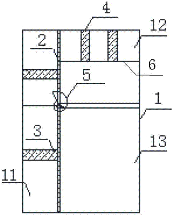
[0043] Such as figure 1 As shown, a soil arch test box includes a box body 1 , a soil arch test chamber 13 arranged in the box body 1 , a variable-diameter arch tool 5 , a horizontal pressurization system 3 and a vertical pressurization system 4 .

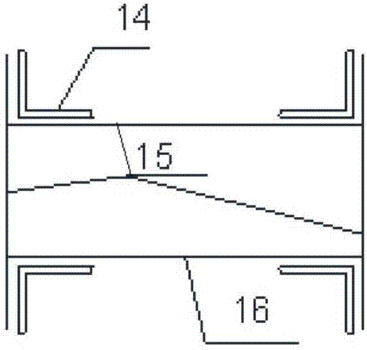
[0044] The box body 1 is a prism with an open lower end. In this embodiment, the box body 1 is a cuboid with a length of 1000 mm, a width of 300 mm and a height of 1500 mm. The side wall of the box body 1 adopts steel plates 15, and the two connected steel plates 15 are fixedly connected by equilateral angle steel 14 and bolts. The connection relationship between each steel plate 15 is as follows figure 2 As shown, the two sides of each equilateral angle steel 14 are respectively attached to two adjacent steel plates 15, and the bolts passing through the angle steel 14 and the steel plates 15 are fixedly connected, and the joints of the two steel plates 15 are sealed with engineering glue.

[0045] Each side wall of the box body...

Embodiment 2

[0067] A kind of test method that adopts the soil arch test box that embodiment 1 provides to measure soil arch effect, comprising:

[0068] Step 1, adjust the position of the horizontal movable plate 2 according to the pile spacing. That is, the horizontal movable plate 2 is pushed to a suitable position along the horizontal guide rail by the horizontal pressurization system 3 to obtain different pile spacings.

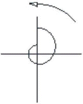
[0069] Step 2, setting the rotation angle of the variable-diameter arch 5 according to the size of the pile diameter. Through the different rotation angles of the variable-diameter arch 5, the side of the deformed arch facing the soil sample has different pile diameters.

[0070] In step 3, soil samples are filled into the soil arch test chamber 13 in layers from top to bottom, and the soil samples of each layer are separated by thin layers of heterogeneous soil samples. The shape of the soil arch structure is reflected by the texture of the heterogeneous soil samp...


PUM

PropertyMeasurementUnit
Rotation angleaaaaaaaaaa

Abstract

The invention discloses a soil arching test box and method, wherein the soil arching test box comprises a box body; a soil arching test chamber for being filled with a soil sample is arranged in the box body, the wall top and at least one side wall of the soil arching test box are provided with movable plates, and also provided with pressurizing systems capable of applying pressure towards the soil arching test chamber to the corresponding movable plates, a diameter-variable arching tool is rotatably arranged on each movable plate of the side wall in a positioning manner, the diameter-variable arching tool is a horizontally distributed cylinder, and at least a part of the cross section of the cylinder is in a spiral shape. The soil arching test box provided by the invention has the advantages of being simple in structure and easiness in observation, the device structure is simplified according to symmetrical principle, and the self-weight of the soil arching test box is reduced effectively. The soil arching test method is easy to operate and accurate in result.

Description

technical field [0001] The invention relates to the field of soil mechanics engineering, in particular to a soil arch test box and a soil arch test method. Background technique [0002] Soil arching effect is a very common phenomenon in nature. In geotechnical engineering, the formation of soil arch refers to the result of uneven displacement of soil under the action of external force, so as to exert its own strength to resist the action of external force. The soil arching effect of the soil behind the pile is the most important mechanical phenomenon in the separated arrangement of piles. Knowing the soil arching effect of the soil behind the pile is helpful for mastering the stress transfer law of the soil behind the pile, the development trend of the plastic zone of the soil around the pile, It is of great theoretical and engineering significance to determine the reasonable pile spacing and ultimate bearing capacity of piles, analyze the interaction mechanism of piles and...

Claims


Application Information

Patent Timeline
IPC IPC(8): G01N3/02G01N3/08
CPCG01N3/02G01N3/08
Inventor 周奇辉刘世明顾章义胡士兵康祺祯刘尊景夏霄王金昌
Owner POWERCHINA HUADONG ENG COPORATION LTD
Learn More