
Paper shredder for large-scale surface flow field measurement

A large-scale, shredder technology, applied in fluid velocity measurement, measurement device, velocity/acceleration/impact measurement, etc., can solve problems such as concentration of spreading, inability to obtain flow velocity, and inability to distribute shredded paper evenly, achieving mechanical Low failure rate, stable and reliable transmission structure

Inactive Publication Date: 2017-08-08
CHONGQING UNIV
View PDF9 Cites 1 Cited by
  • Summary
  • Abstract
  • Description
  • Claims
  • Application Information

AI Technical Summary

Problems solved by technology

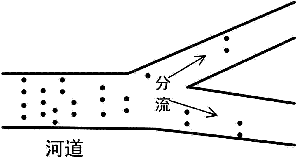
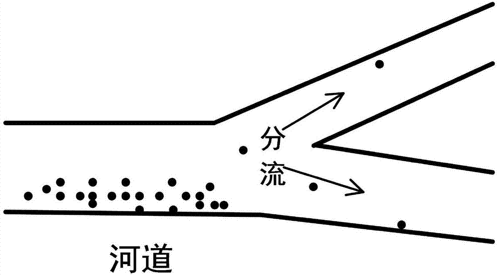
[0002] like figure 1 As shown, a light tracer is placed in the water flow, and the light tracer is a piece of paper, that is, a piece of paper is thrown into the water flow, and then the camera is used for intermittent photography to record the light tracer at different times The position of the object (shards of paper) can be obtained to obtain the trajectory of the light tracer (shards of paper), and the surface flow velocity of the water flow can be obtained after image processing, that is, the resultant velocity of the water flow at different coordinate points (x, y) of the river channel , the speed in the X direction and the speed in the Y direction. The current method of throwing shredded paper is to throw it directly along the river, such as figure 2 As shown, a large number of pieces of paper are gathered near the river, and there are few or no pieces of paper farther away. The pieces of paper cannot be evenly distributed on the surface of the river, resulting in the inability to obtain the flow velocity in some areas of the river.
Since the current method of manually distributing lightweight tracers is used, there is no mechanical device dedicated to evenly distributing light tracers, so it is inevitable for light tracers (shards of paper) to appear concentrated. Phenomenon

Method used


Image

  • Paper shredder for large-scale surface flow field measurement
  • Paper shredder for large-scale surface flow field measurement
  • Paper shredder for large-scale surface flow field measurement

Examples


Embodiment Construction

[0015] In order to make the technical means, creative features, goals and effects achieved by the present invention easy to understand, the technical solutions in the embodiments of the present invention will be clearly and completely described below in conjunction with the accompanying drawings in the embodiments of the present invention.

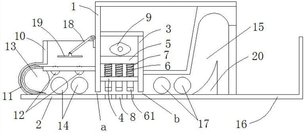
[0016] see image 3 , the specific embodiment is realized by adopting the following technical scheme, which includes a casing 1 and a drive motor installed on the outside of the casing 1 and a paper cutting mechanism driven by the drive motor, a paper storage mechanism and a paper output mechanism, the casing 1 A base plate 2 is provided at the bottom;

[0017] The paper cutting mechanism includes a positioning seat 3 arranged in the cabinet 1, between the bottom edge of both sides of the positioning seat 3 and the bottom plate 2, there are reserved for paper to pass through the paper inlet a and the paper outlet b. The middle part of the...


PUM


Abstract

The invention discloses a paper shredder for large-scale surface flow field measurement. The paper shredder comprises a case (1), a drive motor which is installed outside the case (1), and a paper cutting mechanism, a paper storage mechanism and a paper output mechanism which are driven by the drive motor. A bottom plate (2) is arranged at the bottom of the case (1). The paper cutting mechanism includes a positioning seat (3) arranged in the case (1). A paper inlet (a) and a paper outlet (b) for paper to pass through are reserved between the bottom edges of the two sides of the positioning seat (3) and the bottom plate (2). The paper shredder can be erected on a river channel to realize uniform distribution of paper scraps. If there is a need to scatter a large number of paper scraps all at once, the paper shredder can be dragged at constant speed to scatter a large number of paper scraps. The overall transmission structure is stable and reliable. The overall mechanical failure rate is low.

Description

technical field [0001] The invention relates to the field of experimental equipment related to digital particle image flow field velocimetry technology, in particular to a paper shredder used for large-scale surface flow field measurement. Background technique [0002] like figure 1 As shown, a light tracer is placed in the water flow, and the light tracer is a piece of paper, that is, a piece of paper is thrown into the water flow, and then the camera is used for intermittent photography to record the light tracer at different times The position of the object (shards of paper) can be obtained to obtain the trajectory of the light tracer (shards of paper), and the surface flow velocity of the water flow can be obtained after image processing, that is, the resultant velocity of the water flow at different coordinate points (x, y) of the river channel , the speed in the X direction and the speed in the Y direction. The current method of throwing shredded paper is to throw it ...

Claims


Application Information

Patent Timeline
Patent Type & Authority Applications(China)
IPC IPC(8): G01P5/20B02C18/02B02C18/04B02C23/02
CPCG01P5/20B02C18/02B02C18/04B02C23/02
Inventor 李正浩周杨艾竹吴俊杨美玲李鸿鹄陈凯舒岳阶
Owner CHONGQING UNIV
Learn More