Automatic punching device of cup body of temperature limiter

A technology of stamping equipment and temperature limiter, which is applied in the field of automatic stamping equipment for temperature limiter cups, can solve the problems of high cost, potential safety hazards, low work efficiency, etc. Effect

Inactive Publication Date: 2017-08-11
信宜市翔胜家电科技有限公司
8 Cites 0 Cited by

AI-Extracted Technical Summary

Problems solved by technology

[0002] The temperature limiter has an inner cup body and an outer cup body. At present, the stamping of the cup body is done manually. The worker puts the raw material plate under the punch, and after stamping, the cup body is taken away and put into another raw material plate...

Method used

The raw material plate is stacked on the raw material plate storage rack 2 places, and the horizontal bar 41 of the feeding mechanism 4 is driven by the horizontal reciprocating drive mechanism 42, and moves back and forth along the raw material plate storage rack 2-punching platform 1 direction, in the process , the retrieving manipulator 43 places the raw material plate on the raw material plate storage rack 2 on the raw material plate buffer table 3, and the feeding manipulator 44 places the raw material plate on the raw material plate buffer table 3 on the mold 12 of the punching table...

Abstract

The invention aims to provide an automatic punching device of a cup body of a temperature limiter, wherein the automatic punching device of the cup body of the temperature limiter is low in cost and can replace manual operation of workers, improve efficiency and lower potential safety hazards. The automatic punching device of the cup body of the temperature limiter comprises a punching platform and a feeding mechanism, wherein the punching platform is provided with a punch pin and a die, and the feeding mechanism is used for feeding a raw material plate to the punching plate. A raw material plate storage frame is arranged on the side of the punching platform. A raw material plate temporary storage platform is arranged between the raw material plate storage frame and the punching platform. The feeding mechanism comprises a horizontal rod and a horizontal reciprocating drive mechanism connected with the horizontal rod. A fetching mechanical arm and a feeding mechanical arm are arranged on the horizontal rod in a spaced manner. The feeding mechanical arm is located between the fetching mechanical arm and the punching platform. The movement area of the feeding mechanical arm is located between the raw material plate temporary storage platform and the punching platform. The movement area of the fetching mechanical arm is located between the raw material plate storage frame and the raw material plate temporary storage platform. The horizontal rod is provided with a cup body pushing-down rod which is towards the punching platform and protrudes from the feeding mechanical arm, and the cup body pushing-down rod is higher than the feeding mechanical arm.

Application Domain

Metal-working feeding devicesPositioning devices +2

Technology Topic

ManipulatorLimiter +3

Image

  • Automatic punching device of cup body of temperature limiter

Examples

  • Experimental program(1)

Example Embodiment

[0015] Example 1:
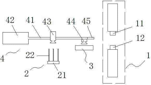
[0016] As shown in the figure, the automatic punching equipment for the temperature limiter cup body in this embodiment includes a punching table 1 provided with a punch 11 and a die 12, and a feeding mechanism 4 for sending the raw material plate to the punching table 1. The punching table 1. There is a raw material plate storage rack 2 on the side, and a flat plate-shaped raw material plate buffer table 3 is arranged in the middle of the raw material plate storage rack 2 and the punching table 1. The top surface of the raw material plate buffer table 3 and the top surface of the mold 12 are on the same level. The raw material board storage rack 2 is composed of a base 21 and a plurality of magnetic rods 22 vertically arranged on the base 21, and the area between the magnetic rods 22 is the area where the raw material board is placed.
[0017] The feeding mechanism 4 includes a horizontal rod 41 and a horizontal reciprocating driving mechanism 42 connected with the horizontal rod 41 (a horizontally placed air cylinder can be used as the role), and the horizontal rod 41 is provided with a feeding manipulator 43 and a feeding manipulator 44 at intervals, wherein feeding The manipulator 44 is located between the reclaiming manipulator 43 and the punching table 1, the moving interval of the feeding manipulator 44 is between the raw material plate buffer table 3 and the punching table 1, and the moving interval of the reclaiming manipulator 43 is the raw material plate storage rack 2 and the raw material Between the plate buffer table 3; the horizontal rod 41 is provided with a cup body pushing rod 45 protruding from the feeding manipulator 44 in the direction of the punching table 1. The cup body pushing rod 45 is higher than the feeding manipulator 44, and lower than the punch 11 in the unpressed state height at time.
[0018] The reclaiming manipulator 43 and the feeding manipulator 44 are both composed of a vertically arranged cylinder and a suction cup fixed on the cylinder piston rod, wherein the vertical stroke of the reclaiming manipulator 43 is greater than that of the feeding manipulator 44 .
[0019] The working principle of the automatic stamping equipment for the temperature limiter cup body is as follows:
[0020] The raw material board is stacked on the raw material board storage rack 2, and the horizontal rod 41 of the feeding mechanism 4 is driven by the horizontal reciprocating drive mechanism 42 to reciprocate along the direction of the raw material board storage rack 2-punching table 1. During this process, the material is taken out. The manipulator 43 places the raw material board on the raw material board storage rack 2 on the raw material board buffer table 3, and the feeding robot 44 places the raw material board on the raw material board buffer table 3 on the die 12 of the punching table 1 for punching; Before feeding, the cup pushing rod 45 protruding from the feeding manipulator 44 pushes the punched cup away from the punching table 1 . The worker only needs to place the raw material board on the raw material board storage rack 2, and collect the finished cup body that has been pushed down. The degree of automation is very high, and because of the double feeding method, it is possible to reduce or avoid a single time. The situation that the raw material sheets that are prone to be fed are overlapped and sent to the punching table 1, which reduces the reject rate.

PUM

no PUM

Description & Claims & Application Information

We can also present the details of the Description, Claims and Application information to help users get a comprehensive understanding of the technical details of the patent, such as background art, summary of invention, brief description of drawings, description of embodiments, and other original content. On the other hand, users can also determine the specific scope of protection of the technology through the list of claims; as well as understand the changes in the life cycle of the technology with the presentation of the patent timeline. Login to view more.

Similar technology patents

Flexible production system for micro die casting fitting grinding detection

ActiveCN110385618AImprove flexible production and management levelhigh degree of automation
Owner:CHONGQING INST OF GREEN & INTELLIGENT TECH CHINESE ACADEMY OF SCI

New energy automobile charger

ActiveCN105598941Ahigh degree of automationlarge bending range
Owner:夏林嘉 +1

Classification and recommendation of technical efficacy words

  • Reduce scrap rate
  • high degree of automation

High-fineness urban three-dimensional modeling method

Owner:星际空间(天津)科技发展有限公司

Bolt machining all-in-one machine

Owner:ANHUI LIUFANG ZHONGLIAN MECHANICAL SHARE
Why Eureka
Try Eureka