Material polishing equipment

A kind of equipment and sliding joint technology, which is applied in the field of material polishing equipment, can solve the problems of complex operation, poor safety performance, and low work efficiency, and achieve the effect of improving safety, improving work efficiency, and reasonable design

Active Publication Date: 2017-08-11
NANTONG TONGYANG MECHANICAL & ELECTRICAL MFR
View PDF7 Cites 3 Cited by
  • Summary
  • Abstract
  • Description
  • Claims
  • Application Information

AI Technical Summary

Problems solved by technology

[0002] Polishing refers to the use of machinery, chemistry or electrochemistry to reduce the surface roughness of the material to obtain a bright and smooth surface. The existing workers usually use a hand-held polishing machine for polishing, which has low work efficiency and manual polishing. Only one polishing head can polish the material individually, which requires repeated operations during polishing, complicated operation and poor safety performance

Method used


Image

  • Material polishing equipment
  • Material polishing equipment
  • Material polishing equipment

Examples


Embodiment Construction

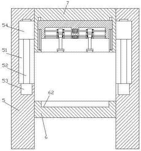
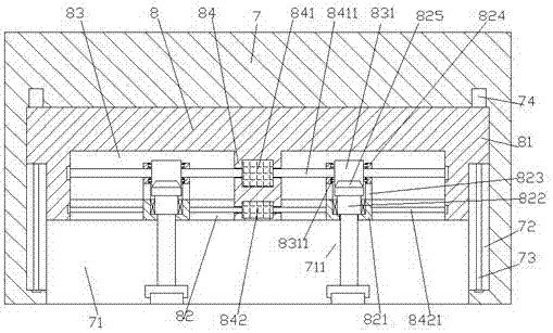
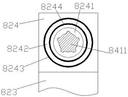
[0023] like Figure 1-Figure 7 As shown, a kind of material polishing equipment of the present invention includes frame bodies 5 correspondingly arranged on the left and right sides and a chassis 6 fixed between the inner sides of the frame bodies 5 on the left and right sides, and the left and right sides above the chassis 6 A polishing part 7 is provided between the inner sides of the frame body 5, and a first sliding joint groove 71 is provided in the bottom end surface of the polishing part 7, and a polishing sliding joint block 8 is smoothly fitted and connected in the first sliding joint groove 71. , the bottom end surface of the polished sliding joint block 8 is provided with a second sliding joint groove 82, and the top of the second sliding joint groove 82 is provided with a transmission cavity 83 that is connected and set, and the second sliding joint groove 82 is provided with There is a partition plate 84 that expands upwards. The top expansion part of the partitio...


PUM


Abstract

The invention discloses material polishing equipment. The material polishing equipment comprises frames correspondingly arranged on the left and right sides and a chassis fixed between inner sides of the frames on the left and right sides; a polishing component is arranged above the chassis and between the inner sides of the frames on the left and right sides, a first sliding connection groove is formed in the end face of the bottom of the polishing component, a polishing sliding connection block is connected into the first sliding connection groove in a smooth fit manner, a second sliding connection groove is formed in the end face of the bottom of the polishing sliding connection block, and a through transferring connection cavity is formed in the top of the second sliding connection groove; a dividing plate extending upwards is arranged between parts of the second sliding connection groove, an extending part on the top of the dividing plate penetrates into the transferring connection cavity, and the tail end of the extending part is fixedly connected with the top end of the interior of the transferring connection cavity; and the second sliding connection groove is divided by the dividing plate into a left guide connection groove and a right guide connection groove, the transferring connection cavity is divided by the dividing plate into a left transferring connection cavity body and a right transferring connection cavity, and a first electric rotating machine is arranged in the position, between the left guide connection groove and the right guide connection groove, of the dividing plate. The material polishing equipment is simple in structure and reasonable in design, the working efficiency is improved, and the equipment using safety is improved.

Description

technical field [0001] The invention relates to the field of polishing equipment, in particular to a material polishing equipment. Background technique [0002] Polishing refers to the use of machinery, chemistry or electrochemistry to reduce the surface roughness of the material to obtain a bright and smooth surface. The existing workers usually use a hand-held polishing machine for polishing, which has low work efficiency and manual polishing. Only one polishing head can polish the material individually, so that repeated operations need to be performed many times during polishing, the operation is complicated, and the safety performance is poor. Contents of the invention [0003] The technical problem to be solved by the present invention is to provide a material polishing equipment, which can solve the above-mentioned problems in the prior art. [0004] The present invention is achieved through the following technical solutions: a material polishing equipment of the pr...

Claims


Application Information

Patent Timeline
Patent Type & Authority Applications(China)
IPC IPC(8): B24B29/00B24B41/02
CPCB24B29/00B24B41/02
Inventor 陈柯
Owner NANTONG TONGYANG MECHANICAL & ELECTRICAL MFR
Why Eureka
Try Eureka