
Anti-fall Beam Reinforcing Device for Hanging Beam Section of Beam Bridge

A reinforcement device and anti-falling beam technology, which is applied in bridges, bridge construction, bridge parts, etc., can solve the problems of bridge use restrictions, falling beams, unfavorable problems, etc., and achieve the goal of improving bending stiffness, bearing capacity, and integrity Effect

Active Publication Date: 2019-11-12
SOUTHEAST UNIV
View PDF8 Cites 0 Cited by
  • Summary
  • Abstract
  • Description
  • Claims
  • Application Information

AI Technical Summary

Problems solved by technology

However, due to the deflection at the junction of the hanging beam and the cantilever end, there will be a break point that is not conducive to driving, and the phenomenon of vehicle jumping is serious, and the phenomenon of beam falling is easy to occur under severe vibrations such as earthquakes and ship collisions, so that the use of the hanging beam system bridge is limited. limit
[0003] At present, there are two methods to solve the problem of falling beams in hanging girder bridges. One is to directly make a continuous girder bridge. For old hanging girder bridges, it is not economical and reasonable to demolish them and rebuild them into continuous girder bridges; another method is to directly connect the hanging girders and cantilever ends with rigid devices, but the release of temperature stress cannot be well controlled, and in Under the action of an earthquake, it is impossible to perform effective shock absorption and energy dissipation
Therefore, there is no very effective solution to the phenomenon of anti-falling beams of hanging girder bridges at present, and it is urgent to propose a new reinforcement device and its measures

Method used


Image

  • Anti-fall Beam Reinforcing Device for Hanging Beam Section of Beam Bridge
  • Anti-fall Beam Reinforcing Device for Hanging Beam Section of Beam Bridge
  • Anti-fall Beam Reinforcing Device for Hanging Beam Section of Beam Bridge

Examples


Embodiment Construction

[0020] The technical scheme of the present invention will be further described below in conjunction with the drawings.

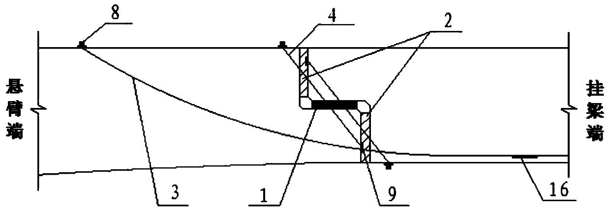
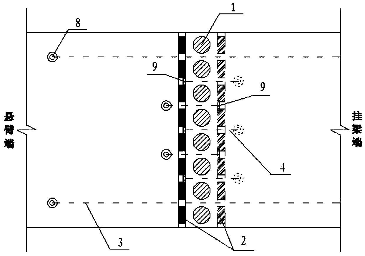
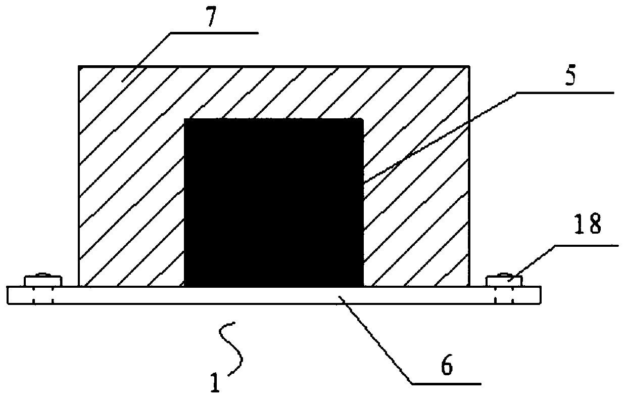
[0021] Such as figure 1 with figure 2 As shown, the cantilever end and the hanging beam end on the beam bridge are placed on each other. This partial structure is usually called a corbel. The corbel structure of the hanging beam is connected with the extended cantilever to form a complete beam bridge. The present invention is a beam-type bridge hanging beam section anti-dropping beam reinforcement device, comprising a plurality of soft steel lead rubber dampers 1 with evenly distributed horizontal intervals between the corbels at the adjacent cantilever ends and the hanging beam ends, and vertical intervals Uniformly distributed high-damping rubber buffer device 2; avoiding the soft steel lead rubber damper 1 and high-damping rubber buffer device 2, staggered stretched between the cantilever end and the hanging beam end are provided with pre-stressed steel stra...


PUM


Abstract

The invention discloses a beam falling prevention reinforcing device of a beam type bridge suspended beam section. The beam falling prevention reinforcing device comprises a plurality of soft steel lead core rubber dampers and a plurality of high-damping rubber buffering devices, wherein the soft steel lead core rubber dampers and the high-damping rubber buffering devices are uniformly distributed between brackets of adjacent cantilever ends and suspended beam ends at intervals. The high-damping rubber buffering devices are vertically arranged, and the soft steel lead core rubber dampers are horizontally arranged. Avoiding from the soft steel lead core rubber dampers and the high-damping rubber buffering devices, reinforcing prestress steel strands and reinforcing prestress steel bars are arranged between the cantilever ends and the suspended beam ends in a staggered and pulling mode. By adoption of the beam falling prevention reinforcing device, the suspended beam ends and the cantilever ends are connected into a whole through the prestress steel bars and connected through the soft steel lead core rubber dampers and the high-damping rubber buffering devices so that the structure can release temperature stress under temperature changes and can further generate energy consumption under violent vibration, and beam falling is prevented; and the prestress steel strands are internally provided with fiber grating sensors which are anchored to beam bodies through retractable anchorage devices, prestress loss can be regularly measured, and the prestress value is adjusted according to the prestress loss.

Description

Technical field [0001] The invention relates to an anti-falling beam reinforcement device for the hanging beam section of a beam type bridge, and is particularly suitable for the design of an anti-falling beam bridge adopting the hanging beam section and strengthening the old hanging beam bridge. Background technique [0002] The hanging girder bridge is a statically determinate structure. Its internal force is not affected by additional deformations such as uneven settlement of the foundation, and no secondary internal force will be generated due to factors such as temperature changes. Compared with simply supported beams, the negative bending moment at the fulcrum reduces the positive bending moment in the middle of the span, which can reduce the beam height; compared with cantilever beams, there is no need for system conversion during the construction process, which saves large tonnage bearings The device is suitable for the cantilever construction method, and the construction...

Claims


Application Information

Patent Timeline
Patent Type & Authority Patents(China)
IPC IPC(8): E01D19/00
CPCE01D19/00
Inventor 王浩邹仲钦茅建校郑文智
Owner SOUTHEAST UNIV
Learn More