
State monitoring and fault diagnosis system for reciprocating type equipment, and application method for state monitoring and fault diagnosis system

A fault diagnosis system and fault diagnosis technology, applied in the testing of machines/structural components, measuring devices, instruments, etc., can solve the problems of large monitoring errors, low diagnostic accuracy, and inability to apply large and medium-sized reciprocating equipment, etc., to achieve small monitoring errors , the effect of high diagnostic accuracy

Pending Publication Date: 2017-08-11
CHINA UNIV OF PETROLEUM (BEIJING)
View PDF8 Cites 1 Cited by
  • Summary
  • Abstract
  • Description
  • Claims
  • Application Information

AI Technical Summary

Problems solved by technology

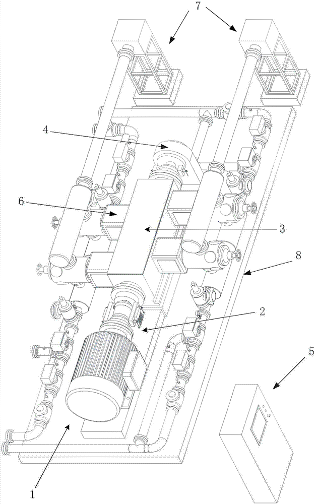
[0008] In order to solve the problems of large and medium-sized reciprocating equipment in the state monitoring and fault diagnosis of the existing large and medium-sized reciprocating equipment, the monitoring error is relatively low, the diagnostic accuracy is low, and it cannot be applied to large and medium-sized reciprocating equipment in more complicated working conditions, and further proposes a State monitoring and fault diagnosis system of reciprocating equipment and its application method

Method used


Image

  • State monitoring and fault diagnosis system for reciprocating type equipment, and application method for state monitoring and fault diagnosis system
  • State monitoring and fault diagnosis system for reciprocating type equipment, and application method for state monitoring and fault diagnosis system
  • State monitoring and fault diagnosis system for reciprocating type equipment, and application method for state monitoring and fault diagnosis system

Examples


Embodiment 1

[0064] For ease of description, the implementation of diagnosis under horizontal misalignment fault is taken as an example to describe in detail, and the implementation of other fault diagnosis is similar to this.

[0065] Firstly, adjust the components corresponding to the fault in the fault realization subsystem 6 according to the research fault and fault degree, and complete the comparison state setting of the diagnosis system. In this embodiment, the intact state is used as the comparison state, and the specific process is as follows:

[0066] Measure the axial and radial alignment data of the first coupling 211 , compare the normal data range value of the reciprocating device body 31 in the driven component subsystem 3 , check and confirm that the data is within the normal range.

[0067] Then, by adjusting or checking the driving subsystem 1, the transmission subsystem 2, the driven component subsystem 3, the load excitation subsystem 4, the measurement and control subsy...


PUM


Abstract

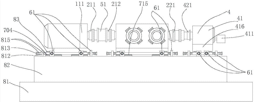
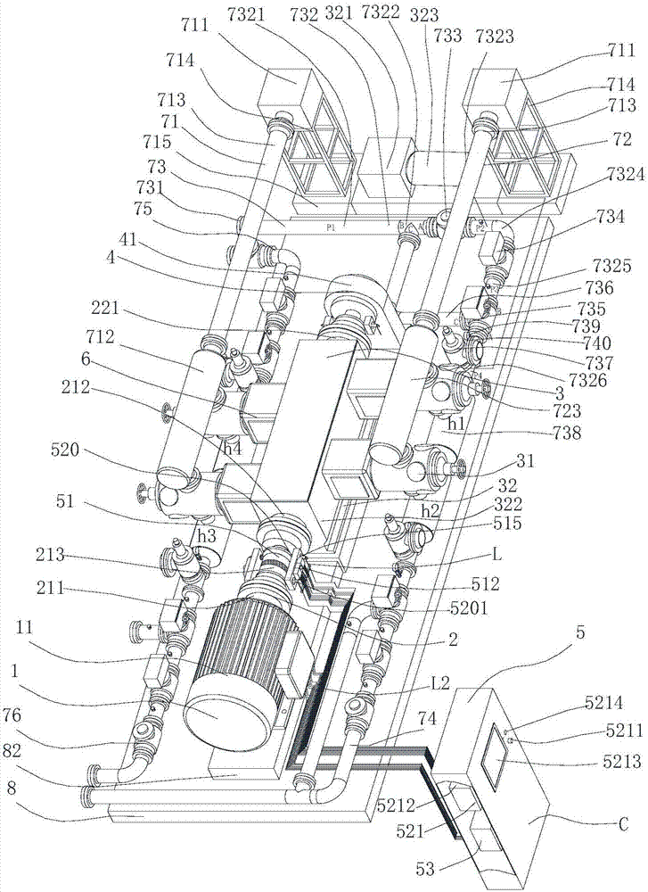
The invention provides a state monitoring and fault diagnosis system for reciprocating type equipment, and an application method for the state monitoring and fault diagnosis system. The system comprises a measurement and control subsystem, a pedestal, a drive subsystem, a transmission subsystem, a driven part subsystem, a load excitation subsystem, a fault implementation subsystem and a variable working condition implementation subsystem, wherein the drive subsystem, the transmission subsystem, the driven part subsystem, the load excitation subsystem, the fault implementation subsystem and the variable working condition implementation subsystem are disposed on the pedestal. The drive subsystem, the driven part subsystem and the load excitation subsystem are sequentially connected in a mechanical and coaxial manner through the transmission subsystem. The fault implementation subsystem is mechanically connected with the driven part subsystem. The variable working condition implementation subsystem is mechanically connected with the fault implementation subsystem. The measurement and control subsystem is electrically connected with the drive subsystem, the driven part subsystem, the load excitation subsystem, and the variable working condition implementation subsystem. The system can reproduce the operation state which is very similar to the state of large-middle size reciprocating type equipment. The system can generate a smaller monitoring error and higher diagnosis precision in the process of state monitoring and fault diagnosis.

Description

technical field [0001] The invention relates to a state monitoring and fault diagnosis system of reciprocating equipment and an application method thereof, belonging to the technical field of equipment fault diagnosis. Background technique [0002] The existing medium-sized (driving power between 150-500kW) and large-scale (driving power greater than 500kW) reciprocating equipment is the key power equipment of petrochemical enterprises. —Mandatory accessory parts” form. Compared with miniature reciprocating equipment with driving power less than or equal to 5kW, the cost of large and medium-sized reciprocating equipment, the criticality of the link, the importance of operating health and the cost of failure are all greatly increased, and unplanned shutdown will cause huge economic losses. [0003] Compared with the existing petroleum and petrochemical medium and large rotating equipment, large and medium-sized reciprocating equipment has different characteristics in terms o...

Claims


Application Information

Patent Timeline
Patent Type & Authority Applications(China)
IPC IPC(8): G01M99/00
CPCG01M99/005G01M99/007
Inventor 段礼祥王文书张来斌王金江
Owner CHINA UNIV OF PETROLEUM (BEIJING)
Learn More