
Digital signal identification method
A digital signal and identification method technology, applied in the field of data analysis, can solve the problems of low analysis efficiency, difficult and cumbersome identification of digital interfaces, and achieve the effect of high signal identification accuracy
- Summary
- Abstract
- Description
- Claims
- Application Information
AI Technical Summary
Problems solved by technology
Method used
Image


Examples
Embodiment 1
[0061] like figure 1 As shown, a digital signal recognition method includes the following steps:
[0062] (1) Offset sampling
[0063] Set the voltage difference between the reference ground of the oscilloscope channel and the ground wire of the object under test to be X volts, and then collect a section of voltage waveform as the waveform to be tested;
[0064] (2) Find the line segment
[0065] Set sampling point interval = 10, that is, the difference between the index values of two adjacent sampling points, that is, sampling every 9 actual sampling points; number of sampling points = 4 = number of sampling segments + 1, two adjacent sampling points The data in between is a section of sampling; the discrete value of the sampling point = 0.1V, the absolute value of the difference between the voltage value of any sampling point and the average voltage value of all sampling points is used to judge the validity of the sampling; the number of filtering points = 3, When used ...
Embodiment 2
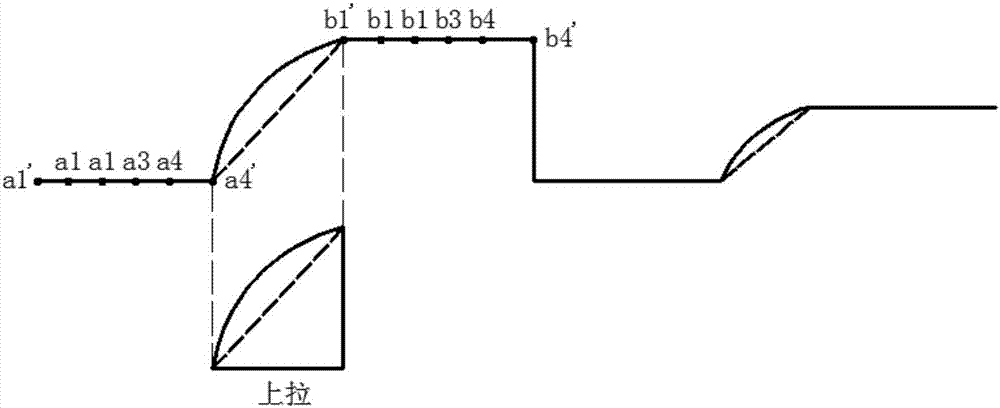
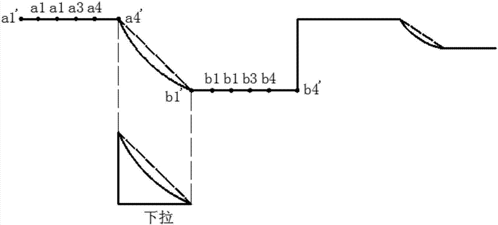
[0094] Embodiment 2: as figure 2 and image 3 as shown, figure 2 for two pull-ups and one transition, image 3 It is two pull-downs and one jump, and the rest are the same as in Embodiment 1, except that: in the step (7), after detection, the above-mentioned line segments meet the following judgment conditions: the number of pull-ups ≥ 0 and the number of pull-downs ≥ 0 And the number of times of pull-up and pull-down ≥ 1 and the number of filtering ≤ 1 and the number of jumps = 3 - the number of pull-ups - the number of pull-down - the number of filtering = 1, so it is a tri-state digital signal.
Embodiment 3
[0095] Embodiment 3: as Figure 4 As shown, the remaining parts are the same as in Embodiment 1, except that the N=5.
[0096] In the present invention, first look for a horizontal line segment with equal level values from the collected waveform data, and traverse all the collected data backwards in this way to find all the line segments; secondly, merge all the line segments and judge that the average voltage value of the line segment is in the Within the preset range; identify the change data between two adjacent line segments again; finally determine the type of signal; in engineering applications, when the identification parameters are manually set according to the actual signal waveform, the computer will automatically record these identification parameter values In order to achieve the purpose of self-learning, it lays the data foundation for automatic matching and identification of parameter values according to the collected waveforms.
[0097] Based on the above, ...
PUM
 Abstract
Description
Claims
Application Information