
Three-dimensional winding core winding device

A technology of three-dimensional wound iron core and winding device, which is applied in the direction of inductance/transformer/magnet manufacturing, electrical components, circuits, etc., which can solve the problems of inconvenient, time-consuming, and inability to adjust the position of the claws, etc., to prevent shaking effect

Active Publication Date: 2018-05-18
CHONGQING WANGBIAN ELECTRIC GRP CORP
View PDF4 Cites 0 Cited by
  • Summary
  • Abstract
  • Description
  • Claims
  • Application Information

AI Technical Summary

Problems solved by technology

[0003] The disadvantages of the existing coiled iron core transformer winding machine are: 1. Using the existing coiled iron core transformer dedicated winding machine, the positioning of the iron core and the positioning of the winding gear are very troublesome. Coil, iron core positioning and winding gear positioning take a lot of time, which is very inconvenient; 2. Because the iron core is fixed sideways, in the process of winding the coil, first of all, two or two of the three iron core single frames The contact parts are wound, but in the prior art, the position of the winding gear needs to be changed back and forth when winding these three places, so the position of the power mechanism also needs to be changed, which is very inconvenient; 3. The existing jaws cannot Adjust the position, and the existing winding gear can only hold the iron core of the same specification, therefore, the existing winding device is not convenient for winding processing of iron cores of different specifications

Method used


Image

  • Three-dimensional winding core winding device
  • Three-dimensional winding core winding device
  • Three-dimensional winding core winding device

Examples


Embodiment Construction

[0025] The present invention will be described in further detail below by means of specific embodiments:

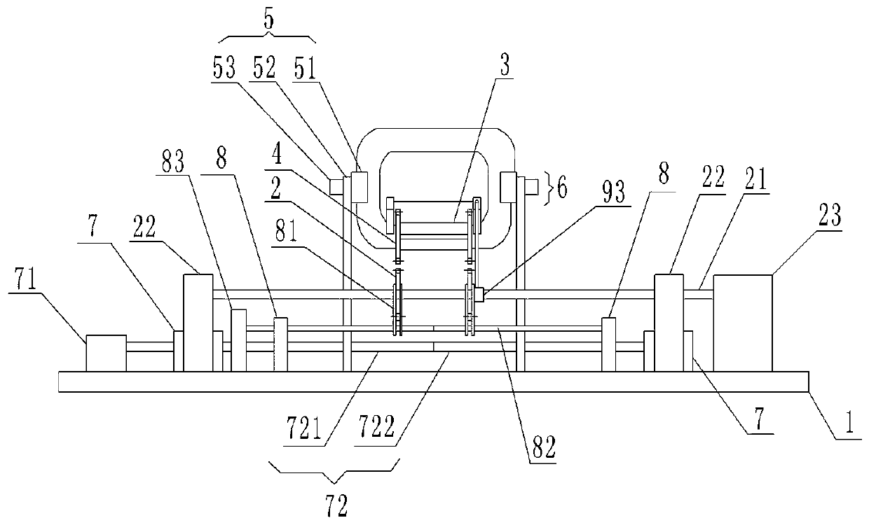
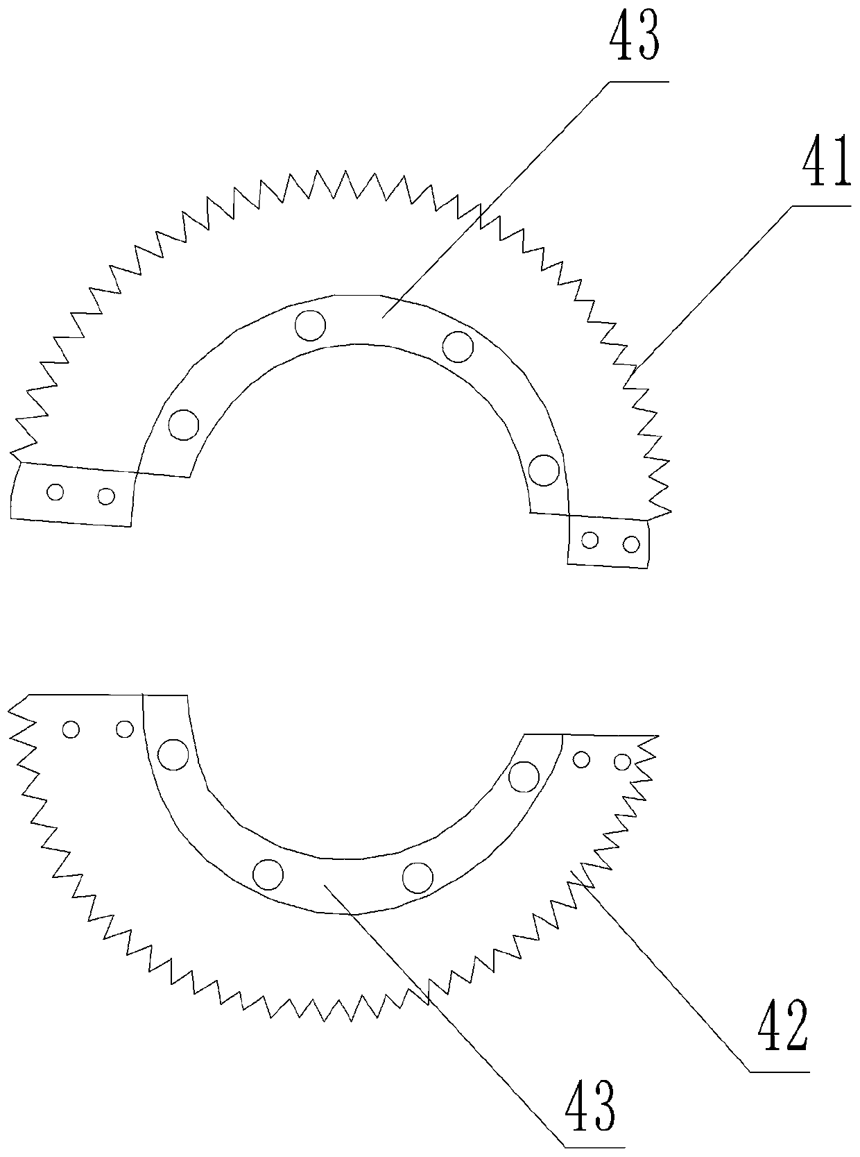
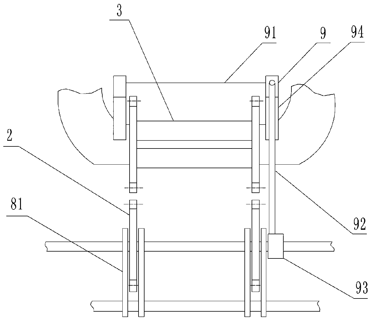
[0026] The reference signs in the drawings of the description include: fixed base 1, driving gear 2, rotating shaft 21, support seat 22, second motor 23, coil sleeve 3, winding gear 4, first semicircular gear 41, second semicircular gear 42. Inner semi-circular ring 43, first claw 5, gripper 51, support plate 52, first motor 53, second claw 6, positioning seat 7, third motor 71, power shaft 72, positive thread of power shaft Section 721, power shaft reverse thread section 722, bearing 8, push plate 81, screw mandrel 82, fourth motor 83, anti-friction plate 9, cutter 91, telescopic rod 92, collar 93, clip 94.

[0027] Such as figure 1 and figure 2As shown, the three-dimensional wound core winding device includes a fixed base 1, a driving gear 2, claws, a coil sleeve 3 that can be sleeved on the iron core, and a winding gear 4 that can be stuck on the coil sleeve 3; the ...


PUM


Abstract

The invention relates to the technical field of winding devices, in particular to a stereoscopic roll-core winding device. The stereoscopic roll-core winding device comprises a fixed base, a power mechanism, a clamping jaw, a coil sleeve and winding gears, wherein the clamping jaw is slidingly connected on the fixed base, and connected with a first motor; a third motor and positioning seats are arranged on the fixed base; a power shaft driven by the third motor is rotationally connected on the positioning seats; the power shaft penetrates through the lower part of the clamping jaw; when the power shaft rotates, the clamping jaw can clamp or loosen a core; each winding gear comprises a first semicircular gear and a second semicircular gear which are connected by screw threads; inner walls of the first semicircular gears and the second semicircular gears are connected with inner semicircular rings; the power mechanism comprises driving gears engaged with the winding gears; sliding keys in the centers of the driving gears are connected with a rotating shaft; and an adjusting part for adjusting the driving gears is arranged on the rotating shaft. With the adoption of the scheme, positioning of the core and the winding gears is facilitated; winding can be performed on pairwise contact parts of three core frames in the same position; and cores in different specifications can be machined.

Description

technical field [0001] The invention relates to the technical field of winding devices, in particular to a three-dimensional wound iron core winding device. Background technique [0002] The three-dimensional wound core transformer is generally a triangular three-dimensional iron core composed of three iron core single frames with the same geometric size. First, the iron core is fixed on the claws, and then the coil is wound on the iron core single frame. parts. The principle of the three-dimensional winding iron core transformer winding machine is: put the position where the iron core single frame is in contact with each other in a coil sleeve, and then hoop the two winding gears on the coil sleeve. The existing winding gear is composed of two It is composed of two semicircular gear rings. When installing, clamp the two gear rings on the coil sleeve and then fix it with screws, and then pull one end of the coil to the coil sleeve to fix it. The power mechanism drives the w...

Claims


Application Information

Patent Timeline
Patent Type & Authority Patents(China)
IPC IPC(8): H01F41/064
Inventor 杨泽民杨林杨德文
Owner CHONGQING WANGBIAN ELECTRIC GRP CORP
Learn More