Mounting method capable of resisting vortex-induced vibration and damping vibration of fan tower tube

A technology of vortex-induced vibration and installation method, which is applied in the direction of wind power engine, machine/engine, wind power motor combination, etc., which can solve the problems of hidden dangers, falling off of the tower, displacement of the tower section, etc., so as to reduce the vibration amplitude and clear the design concept , Reduce the effect of vortex induced vibration effect

Inactive Publication Date: 2017-08-15
北京唐浩电力工程技术研究有限公司
View PDF8 Cites 8 Cited by
  • Summary
  • Abstract
  • Description
  • Claims
  • Application Information

AI Technical Summary

Problems solved by technology

During the installation process of the fan tower, since the outer wall of the fan tower is smooth and columnar, each tower section will produce a relatively strong vortex-induced vibration effect, which will cause the tower section to shift or even fall off. serious hazards in the process

Method used


Image

  • Mounting method capable of resisting vortex-induced vibration and damping vibration of fan tower tube
  • Mounting method capable of resisting vortex-induced vibration and damping vibration of fan tower tube
  • Mounting method capable of resisting vortex-induced vibration and damping vibration of fan tower tube

Examples


Embodiment 1

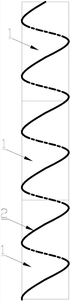
[0062] Such as figure 1 , Figure 5 to Figure 7 As shown, in this embodiment, a vortex-induced vibration damper for installation of a fan tower is introduced. The fan tower includes a multi-section tower section 1 installed sequentially from bottom to top; from the top of the top tower section 1 to the There is a shock-absorbing rope 2 extending downward, and the shock-absorbing rope 2 is spirally arranged around the outer wall of the tower tube. fixed.

[0063] This embodiment also introduces an installation method for anti-vortex-induced vibration and shock absorption of a wind turbine tower. The wind turbine tower includes multi-section tower sections 1 installed sequentially from bottom to top; Install at least one shock-absorbing rope 2 on the outer periphery of the top tower section, the shock-absorbing rope 2 is arranged around the outer wall of the tower in a spiral shape, and the lower end of the shock-absorbing rope 2 is fixedly connected to the bottom of the tower...

Embodiment 2

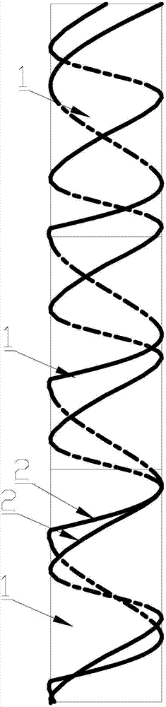
[0079] The difference between this embodiment and the first embodiment above is that: figure 2 As shown, a plurality of shock absorbing ropes 2 are installed at equal intervals from the top outer circumference of the top tower section 1, and each shock absorbing rope 2 is arranged spirally around the outer wall of the tower, and each spiral shock absorbing rope 2 Equally spaced and extending in the same shape, the lower ends of the shock absorbing ropes 2 and the outer circumference of the bottom of the lowest tower section 1 are installed and fixed at equal intervals.

[0080] Preferably, in this embodiment, the outer circumference of the tower is coiled with a plurality of equally spaced, helical shock-absorbing ropes 2, and each shock-absorbing rope 2 is distributed on the outer circumference of the tower at equal intervals, and the adjacent shock-absorbing The distances between the ropes 2 are set equally. By increasing the number of shock-absorbing ropes wound around th...

Embodiment 3

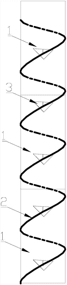
[0082] The difference between this embodiment and the first and second embodiments above is that: image 3 As shown, a plurality of auxiliary shock-absorbing parts 3 are threaded on the shock-absorbing rope 2, and the auxiliary shock-absorbing parts 3 are made of a plate, and the middle part of the plate is provided with a mounting hole 7 for the shock-absorbing rope to pass through, so that each auxiliary The shock-absorbing elements 3 are mounted on the shock-absorbing rope 2 at equal intervals.

[0083] By arranging a plurality of auxiliary shock absorbers pierced on the shock absorbing rope, the airflow around the tower can further change the flow direction under the action of the auxiliary shock absorbers, so that the impact force of the airflow around the tower on the tower can be further improved. The reduction effectively reduces the vibration amplitude of the tower and further improves the anti-vortex-induced vibration effect during the installation of the tower.

[...


PUM


Abstract

The invention relates to a mounting method capable of resisting vortex-induced vibration and damping vibration of a fan tower tube. The fan tower tube comprises a plurality of tower tube sections which are sequentially mounted from bottom to top, wherein after each stage of the tower tube is mounted, at least one vibration damping rope is mounted at the periphery of the top of the tower tube section at the topmost end; and the vibration damping rope is spirally arranged around the outer wall of the tower tube, and the lower end of the vibration damping rope is fixedly connected with the bottom of the tower tube or tower tube mounting ground to provide vibration buffer resisting for the tower tube. With the adoption of the method, the spiral vibration damping rope is arranged around the periphery of the tower tube for guiding gas flow at the periphery of the tower tube to move in the axial direction of the vibration damping rope, so that the purpose of changing a gas flow direction on the outer wall of the tower tube and enabling the gas flow to flow from the horizontal direction to the vertical direction is achieved, and therefore, the air flow at the periphery of the tower tube is in the vertical spiral direction, wind power acting force of the tower tube is reduced, and the purpose of reducing vortex-induced vibration effect in a mounting process of the tower tube is finally achieved.

Description

technical field [0001] The invention relates to a tower of a wind power generator, in particular to a vortex-induced vibration damper for installing a wind turbine tower, and also relates to a method for installing a wind turbine tower against vortex-induced vibration and damping. Background technique [0002] From the perspective of fluid, any non-streamlined object will alternately generate vortices on both sides of the object that are separated from the surface of the structure at a certain constant flow rate, and the vortices constitute the vortex-induced vibration effect. During the installation process of the fan tower, since the outer wall of the fan tower is smooth and columnar, each tower section will produce a relatively strong vortex-induced vibration effect, which will cause the tower section to shift or even fall off. There are more serious hidden dangers in the process. [0003] In view of the above-mentioned technical defects, this application is proposed. ...

Claims


Application Information

Patent Timeline
Patent Type & Authority Applications(China)
IPC IPC(8): F03D9/25F03D13/20F03D80/00
CPCF05B2240/912F05B2260/96Y02E10/72Y02E10/728
Inventor 张羽冯克瑞刘峰宋利宇辛克锋刘志文马泳吏张磊鲁志平戴幸泽宫永立杨明明程学文尹子栋
Owner 北京唐浩电力工程技术研究有限公司
Why Eureka
Try Eureka