Swing type air guide device based on crankshaft

An air guide device and swing-type technology, which is applied in the field of swing-type air guide devices, can solve the problems that the airflow velocity and direction cannot be changed, the hot air or cold air cannot be transported, and the utilization rate of hot or cold air is low, so as to achieve change The effect of air inlet speed and airflow direction change

Inactive Publication Date: 2018-09-18
扬州益洋科技发展有限公司
View PDF0 Cites 0 Cited by
  • Summary
  • Abstract
  • Description
  • Claims
  • Application Information

AI Technical Summary

Problems solved by technology

[0002] Air guide devices can be used in refrigeration equipment, drying equipment, fans and other equipment that require air guide. The position of the existing air guide plate is fixed, and the air flow passes through the air guide plate from a certain direction, causing the air guide plate to go out. The airflow direction of packaging and testing is fixed, and the hot airflow or cold airflow cannot be evenly delivered to every space in the device. The airflow velocity and direction cannot be changed, resulting in low usage of hot airflow or cold airflow

Method used


Image

  • Swing type air guide device based on crankshaft
  • Swing type air guide device based on crankshaft
  • Swing type air guide device based on crankshaft

Examples


Embodiment Construction

[0020] The present invention will be further illustrated below in conjunction with the accompanying drawings and specific examples. The examples are implemented on the premise of the technical solutions of the present invention. It should be understood that these examples are only used to illustrate the present invention and are not intended to limit the scope of the present invention.

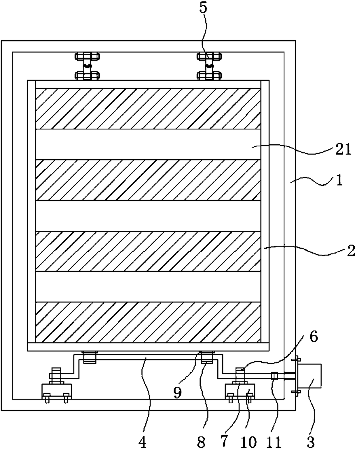
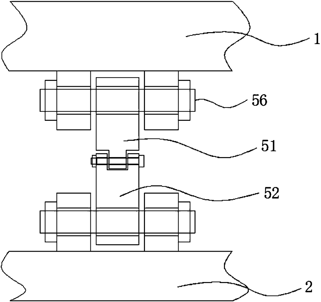
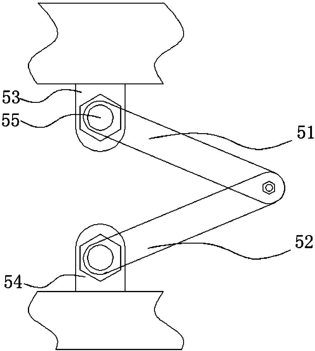
[0021] Such as Figure 1 to Figure 3 As shown, a crankshaft-based oscillating air guide device includes a mounting frame 1, an air guide plate 2, a driving device 3, a crankshaft 4 and a connecting rod mechanism 5, and the driving device 3 is connected to the crankshaft 4 in a transmission manner. Both ends are provided with a first bearing 6 and a first bearing seat 7, the first bearing 6 is arranged in the first bearing seat 7, a second bearing 8 is arranged on the crankshaft 3, and the second bearing is located on the bottom surface of the wind deflector 2 The position above 8 is provided w...


PUM


Abstract

The invention discloses a swing type air guide device based on a crankshaft. The swing type air guide device comprises a mounting frame, an air guide plate, a driving device, the crank shaft and connecting rod mechanisms, wherein the driving device is in transmission connection with the crankshaft, each of the two ends of the crankshaft is provided with a first bearing and a first bearing block, and the first bearings are arranged in the first bearing blocks; second bearings are arranged on the crankshaft, second bearing blocks are arranged at the positions, located on the second bearings, ofthe bottom surface of the air guide plate, and the second bearings are arranged in the second bearing blocks; and one ends of the connecting rod mechanisms are hinged to the upper surface of the air guide plate, and the other ends of the connecting rod mechanisms are hinged to the top wall of the mounting frame. According to the swing type air guide device based on the crankshaft, the air guide pate swings up and down under the driving of the rotary crankshaft, so that the air inlet direction is adjusted up and down along with the swing of the air guide plate, and uniform air inlet is realized; and the rotating speed of the crankshaft is controlled by adjusting the rotating speed of the driving device, so that the swing frequency of the air guide plate is changed, and the air inlet speed and the air flow direction are changed.

Description

technical field [0001] The invention belongs to the technical field of air guiding devices, and in particular relates to a swinging type air guiding device based on a crankshaft. Background technique [0002] Air guide devices can be used in refrigeration equipment, drying equipment, fans and other equipment that require air guide. The position of the existing air guide plate is fixed, and the air flow passes through the air guide plate from a certain direction, causing the air guide plate to go out. The airflow direction of packaging and testing is fixed, and the hot airflow or cold airflow cannot be evenly delivered to every space in the device. The airflow velocity and direction cannot be changed, resulting in a low utilization rate of hot airflow or cold airflow. Contents of the invention [0003] Purpose of the invention: Aiming at the deficiencies in the prior art, the purpose of the present invention is to provide a crankshaft-based swing-type air guiding device. ...

Claims


Application Information

Patent Timeline
Patent Type & Authority Applications(China)
IPC IPC(8): F25D17/04F26B21/00F04D29/40F24F13/14
CPCF25D17/04F04D29/403F24F13/1426F24F2013/1433F26B21/004
Inventor 郁丁丁
Owner 扬州益洋科技发展有限公司
Why Eureka
Try Eureka