A resonance smoke box and its method for enhancing heat exchange

The technology of a smoke box and a resonance cavity is applied in the field of resonance smoke box and its enhanced heat exchange, which can solve the problems of the reduction of heat exchange efficiency of smoke pipes, the limitation of heat exchange efficiency by the flow rate of flue gas, and the inability to apply to large-diameter smoke pipes, etc. To achieve the effect of easy adjustment of flue gas heat exchange efficiency, simple structure and good self-cleaning ability

Active Publication Date: 2020-09-08
苏州博墨热能产品有限公司
View PDF7 Cites 0 Cited by
  • Summary
  • Abstract
  • Description
  • Claims
  • Application Information

AI Technical Summary

Problems solved by technology

[0003] The purpose of the present invention is to solve the problems that the heat exchange efficiency of the smoke pipe is reduced due to the high thermal resistance, the heat exchange efficiency is limited by the flue gas flow rate, and the existing measures for improving the heat exchange efficiency cannot be applied to the large diameter smoke pipe. Carry out determined research to provide a resonance smoke box and its method of enhancing heat transfer. The resonance smoke box is connected to the convection heat exchange device inside the boiler and the flue outside the boiler for conveying flue gas tail gas. The flue gas at a certain speed The flow generates self-excited oscillation in the resonant smoke box and makes this oscillation conduct to the convection heat exchange device behind the flue gas stroke, so that the heat exchange of the flue gas in the entire stroke is strengthened

Method used


Image

  • A resonance smoke box and its method for enhancing heat exchange
  • A resonance smoke box and its method for enhancing heat exchange
  • A resonance smoke box and its method for enhancing heat exchange

Examples


Embodiment 1

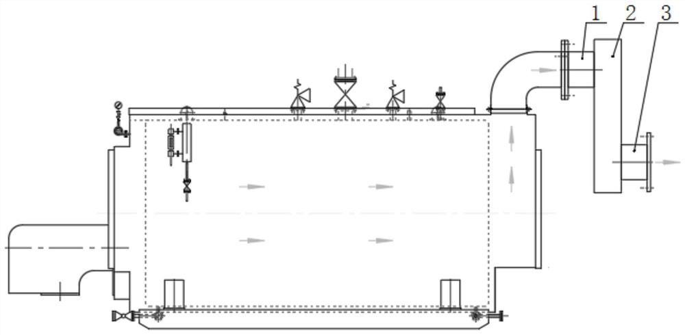
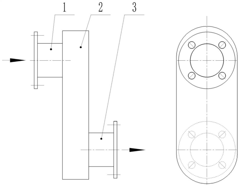
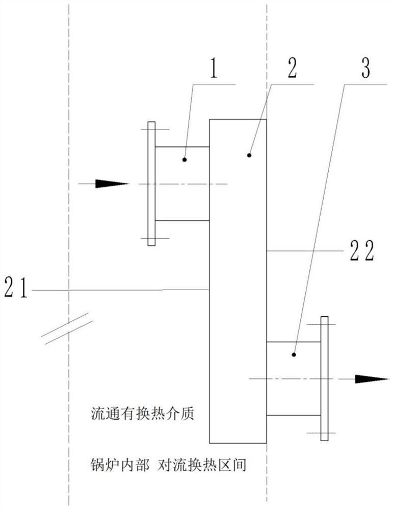
[0087] Such as figure 1 As shown, a resonance smoke box and a heat exchange method using the resonance smoke box, the resonance smoke box is connected to the convection heat exchange device (mainly heat exchange tube) inside the boiler and the flue gas used to transport flue gas and tail gas outside the boiler The resonant smoke box includes the flue gas inlet 1, the flue gas outlet 3, and the resonance cavity 2 between them. The high-temperature flue gas circulates in the heat exchange tube, and the flue gas tail gas formed after convective heat exchange passes through the flue gas. The inlet 1 enters the resonance cavity 2, and enters the flue through the flue gas outlet 3. Wherein, all parts of the resonant cavity 2 enter into the convective heat exchange section of the boiler, and cold water circulates between the heat exchange tubes and the external of the resonant cavity 2 .

[0088] The resonance smoke box is made of alloy steel as a whole, and the cross-sectional area o...

Embodiment 2

[0091] The structure and heat exchange method of the resonant smoke box are consistent with the embodiment 1, the only difference is that a row of reinforcing ribs are respectively arranged in the length direction (horizontal direction) and width (longitudinal) direction of the rear wall surface 22, and the material of the reinforcing ribs is alloy steel. Two rows of reinforcing ribs respectively extend from the middle of the length and width of the rear wall 22, dividing the rear wall 22 into four parts.

[0092] The width of the reinforcing rib in the length direction is 0.05m, and the thickness is 0.04m; the width of the reinforcing rib in the width direction is 0.04m, and the thickness is 0.04m.

Embodiment 3

[0094] The structure and heat exchange method of the resonant smoke box are consistent with Embodiment 1, the only difference is that, as Figure 4 As shown, three rows of reinforcing ribs are evenly arranged in the length direction (horizontal direction) and width (longitudinal) direction of the rear wall surface 22 respectively, and the material of the reinforcing ribs is aluminum.

[0095] In the length direction, the rib in the center has a width of 0.06m and a thickness of 0.04m; the ribs on both sides have a width of 0.05m and a thickness of 0.02m.

[0096] In the width direction, the rib in the center has a width of 0.05m and a thickness of 0.04m; the ribs on both sides have a width of 0.04m and a thickness of 0.02m.


PUM


Abstract

The invention provides a resonance flue gas box and an enhanced heat exchange method of the resonance flue gas box. The resonance flue gas box comprises a flue gas inlet (1), a flue gas outlet (3) anda resonance cavity (2) located between the flue gas inlet (1) and the flue gas outlet (3). The flue gas inlet (1) is connected with a convective heat exchange device inside a boiler, the flue gas outlet (3) is connected with a flue which is located outside the boiler and used for conveying tail flue gas, high-temperature flue gas circulates in the convective heat exchange device, and tail flue gas which is subjected to convective heat exchange enters the resonance cavity (2) through the flue gas inlet (1) and enters the flue through the flue gas outlet (3). According to the resonance flue gasbox, flue gas enters the resonance cavity through the flue gas inlet, flue gas flow at the certain speed produces self-exciting oscillation in the resonance cavity, and the oscillation is transferredto the convective heat exchange device behind a flue gas stroke, flue gas heat exchange in the whole stroke is enhanced, soot is difficultly accumulated through flue gas which is oscillated due to resonance, the good self-cleaning ability is achieved, and convenience is brought to use of the boiler.

Description

technical field [0001] The invention belongs to the technical field of industrial boilers and flue gas / water heat exchangers, and in particular relates to a resonance smoke box and a method for enhancing heat transfer thereof. Background technique [0002] In the smoke pipe flue gas / water heat exchange device, the heat exchange on the flue gas side has a relatively large thermal resistance, so the main measures to improve the efficiency of this type of heat exchange device are to reduce the heat exchange thermal resistance on the flue gas side and strengthen the Heat exchange on the gas side. For the traditional flue-tube heat exchange device, the common practice is to use threaded flue flue pipe and insert spoilers in the pipe to realize the disturbance of flue gas, so as to achieve the purpose of enhancing heat transfer. Among them, the threaded flue pipe can only destroy and disturb the surrounding flue gas, and its strengthening ability is weak, and its heat transfer co...

Claims


Application Information

Patent Timeline
Patent Type & Authority Patents(China)
IPC IPC(8): F23J15/06F23J13/00
CPCY02E20/30
Inventor 王磊
Owner 苏州博墨热能产品有限公司
Why Eureka
Try Eureka