A slightly eccentric swinging flue gas turbulence device and a method for enhancing flue gas heat exchange
A technology of eccentric swing and flow turbulence device, which is applied in the direction of exhaust gas exhaust device, combustion method, lighting and heating equipment, etc., which can solve the problem that the heat transfer efficiency is limited by the flue gas flow rate and cannot be applied to large-diameter smoke pipes, and the heat transfer efficiency of smoke pipes Reduce other problems, achieve the effect of simple manufacturing process, good self-cleaning ability, and low steel consumption
- Summary
- Abstract
- Description
- Claims
- Application Information
AI Technical Summary
Problems solved by technology
Method used
Image
Examples
Embodiment 1
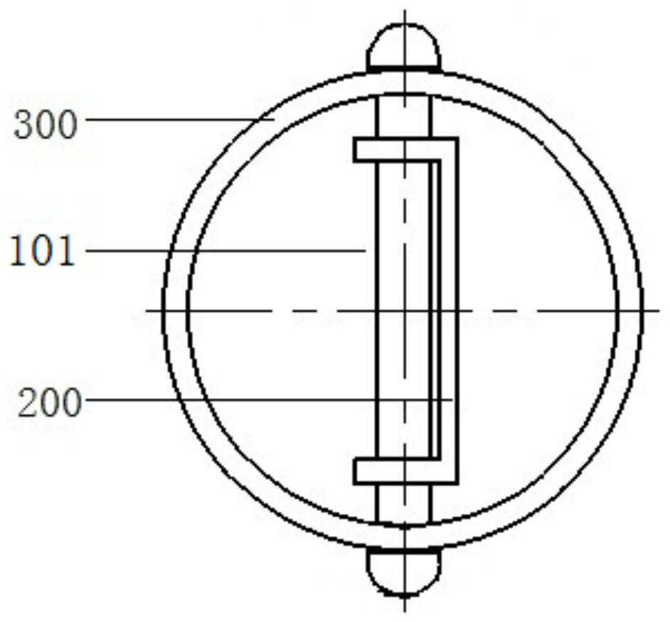
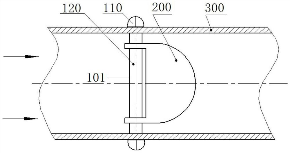
[0085] Such as figure 1 and figure 2 As shown, a flue gas turbulence device of a slightly eccentric swing type and a method for enhancing the heat exchange of flue gas by using the turbulence device, the smoke pipe 300 is a light pipe with a length of 1.1m and a diameter of 159mm (or 108mm), located between the flue gas / The convective heat exchange area of the water heat exchange device.
[0086] The spoiler includes a spoiler 200 that is slightly eccentrically arranged and can rotate along the positioning axis I 101, and a positioning axis I 101 that fixes the spoiler 200 in the smoke pipe 300. The diameters match.
[0087] The smoke turbulence device fixes the spoiler 200 in the smoke pipe 300 through the integrated positioning shaft I 101 passing through the inside of the smoke pipe 300 . The positioning shaft I 101 includes fasteners I 110 at both ends and a shaft body I 120 connecting the fasteners at both ends, through the small through hole on the smoke pipe 300 ...
Embodiment 2
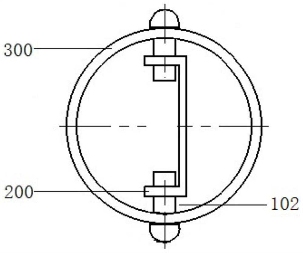
[0092] Such as image 3 and Figure 4 As shown, the structure of the flue gas turbulence device is the same as that of Embodiment 1, the only difference is that the integrated positioning shaft II 102 is replaced by the segmented positioning shaft II 102 passing through two opposite walls of the smoke pipe 300 .
Embodiment 3
[0094] Such as Figure 5 and Figure 7 As shown, the structure of the flue gas turbulence device is consistent with that of Embodiment 1, the only difference is that the positioning shaft III103 is fixed in the smoke pipe 300 by means of a slot, without penetrating through the wall of the smoke pipe 300 . The positioning shaft III 103 is an independent shaft body, the two ends of the shaft body are spherical structures, and are in contact with the inner wall of the smoke pipe 300; the main part of the shaft body is used as the supporting structure of the flow turbulence device.
PUM
 Abstract
Description
Claims
Application Information
 - R&D
- Intellectual Property
- Life Sciences
- Materials
- Tech Scout
- Unparalleled Data Quality
- Higher Quality Content
- 60% Fewer Hallucinations
Browse by: Latest US Patents, China's latest patents, Technical Efficacy Thesaurus, Application Domain, Technology Topic, Popular Technical Reports.
© 2025 PatSnap. All rights reserved.Legal|Privacy policy|Modern Slavery Act Transparency Statement|Sitemap|About US| Contact US: help@patsnap.com


