
Brake cable releasing mechanism

A technology of releasing mechanism and brake line, which is applied in the direction of brake actuator, gear shifting mechanism, mechanical equipment, etc., can solve the problems of inconvenient use of medical pendant, single handle design, unergonomic and other problems

Active Publication Date: 2017-08-15
MAQUET SUZHOU
View PDF14 Cites 1 Cited by
  • Summary
  • Abstract
  • Description
  • Claims
  • Application Information

AI Technical Summary

Problems solved by technology

[0004]The manual control mechanism can only operate in one direction, that is to say, the handle can only realize the pull-down action. Two-handed operation or one-handed laborious operation is required, which will cause inconvenience in the use of medical pendants
Moreover, the handle design of the manual control mechanism is single, which does not conform to ergonomics.

Method used


Image

  • Brake cable releasing mechanism
  • Brake cable releasing mechanism
  • Brake cable releasing mechanism

Examples


Embodiment Construction

[0034] The technical solution of the present invention will be further described in non-limiting detail below in conjunction with preferred embodiments and the accompanying drawings. The positional relationship of the front, back, left, and right, up and down according to the present invention is based on the illustrated orientation.

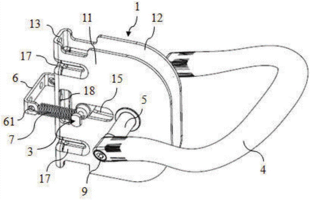
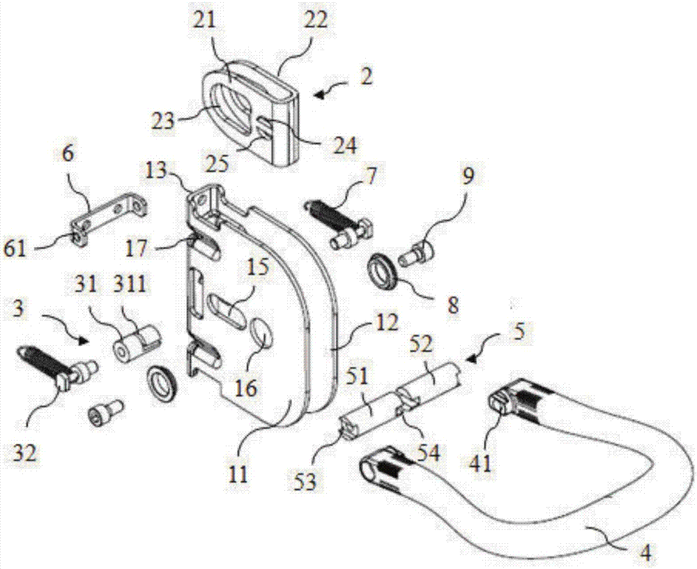
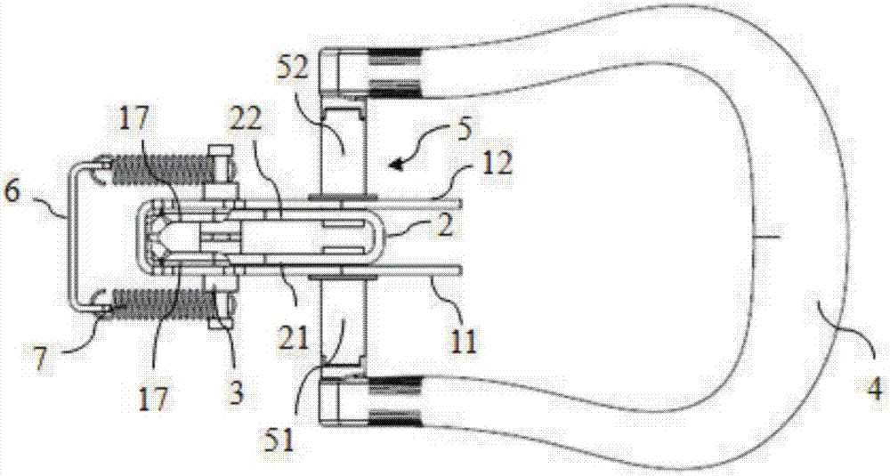
[0035] The invention discloses a brake line release mechanism, which is used for lifting and lowering the box body of a medical pendant and locking at any position. The brake wire release mechanism is installed at the end of the box body of the pendant tower. The two gas springs are located at the elbow joint of the suspension tower, one end of the brake cable is connected with the release heads of the two gas springs, and the other end passes through the box body of the suspension tower and is connected with the brake cable release mechanism. Preferably, the brake cable is a Bowden cable.

[0036] Such as Figure 1 to Figure 7 As shown, the brake ...


PUM


Abstract

The invention discloses a brake cable releasing mechanism. The brake cable releasing mechanism comprises a shifting assembly installed on a supporting base and used for controlling position shift, and the shifting assembly comprises a handle, a rotary shaft matched with the handle and a rotary block connected with the rotary shaft. The shifting assembly further comprises a slide shaft used for being connected with a brake cable, a special-shaped open groove is formed in the rotary block, and the slide shaft is sleeved with the special-shaped open groove. According to the brake cable releasing mechanism, when the handle is downwards pulled or upwards pushed, the brake cable can be released, and smooth lifting of a medical tower crane can be achieved.

Description

Technical field [0001] The invention belongs to the field of medical suspension towers, and specifically relates to a brake line release mechanism of the suspension tower. Background technique [0002] When using a medical pendant, the position of the pendant box needs to be smoothly raised and lowered according to the user's operating requirements. [0003] CN103345294B discloses a manual control mechanism, which is used to release the Bowden wire, that is, the brake wire, to achieve the function of lifting the tower. When the handle is pulled down, the handle turns to drive the Bowden wire release head to turn clockwise, pull the Bowden wire to the right, release the gas spring or other locking elements, thereby opening the movement joints of the medical pendant, making the medical pendant upward or downward movement. [0004] The manual control mechanism can only be operated in one direction, that is, the handle can only be pulled down. When the telescopic element needs to be re...

Claims


Application Information

Patent Timeline
Patent Type & Authority Applications(China)
IPC IPC(8): F16D65/14A61G12/00F16D127/04
CPCF16D65/14A61G12/002F16D2127/04
Inventor 张伟刘向蕾黄家胜许春霞黎群华
Owner MAQUET SUZHOU
Learn More