Worm wheel gear tooth axial center measuring device and measuring method thereof

A technology of worm gear teeth and distance measuring device, which is applied to measuring devices, mechanical measuring devices, and mechanical devices, etc., can solve the problems of inaccurate quantification of assembly matching data, unqualified worm gears, hidden dangers of products, etc., so as to improve the efficiency of the assembly process. , The effect of reducing the cost of combination and improving the efficiency of assembly

Active Publication Date: 2017-08-15
CHINA ELECTRONICS TECH GRP CORP NO 14 RES INST
View PDF23 Cites 4 Cited by
  • Summary
  • Abstract
  • Description
  • Claims
  • Application Information

AI Technical Summary

Problems solved by technology

[0002]In the assembly process of traditional military and civilian worm gear transmissions, due to the lack of means to quantify the median position of the worm gear teeth, the diameter of the worm gear is entered, and the worm gear axis is gradually increased or decreased Gaskets are used to identify whether the worm gear and worm are centered (the center line coincides), and whether the contact area is symmetrical. This process is mainly based on estimation and adjustment in traditional assembly, which cannot be accurately quantified. The coherent linearity of the position is not good, and there will be irregular states such as the position of the meshing plaque from left to right, which will cause the assembly process to fall into a pause in troubleshooting, and even cause unqualified worm gears to enter the assembly, resulting in unnecessary troubleshooting and disassembly during the process. And it brings hid...

Method used


Image

  • Worm wheel gear tooth axial center measuring device and measuring method thereof
  • Worm wheel gear tooth axial center measuring device and measuring method thereof
  • Worm wheel gear tooth axial center measuring device and measuring method thereof

Examples


Embodiment Construction

[0032] The content of the present invention will be further described in detail below in conjunction with the accompanying drawings.

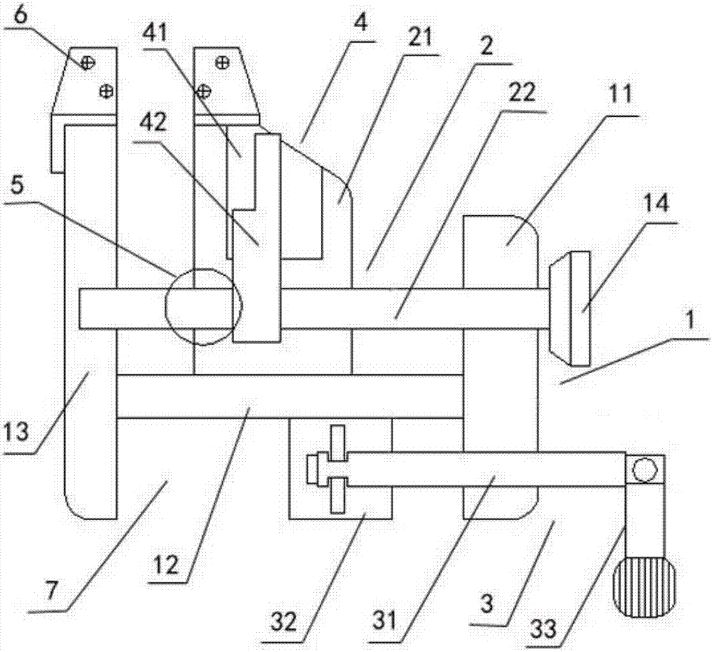
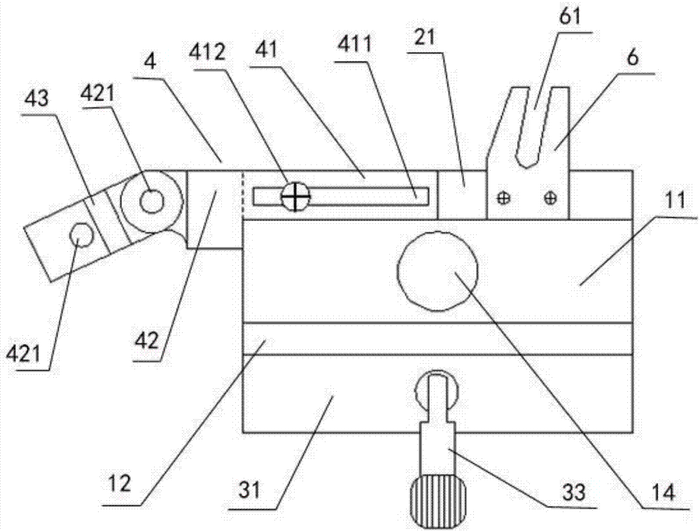
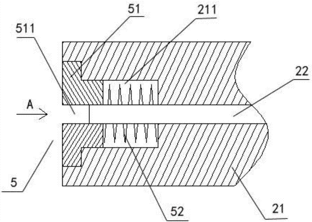
[0033] Such as figure 1 and 4 As shown, a worm gear gear axial centering device includes a bracket 1 , a sliding mechanism 2 , a clamping mechanism 3 , a distance measuring device 9 , and a dial gauge 8 . The distance measuring device 9 can be preferably a digital caliper, which is convenient for accuracy and flexibility of measurement. The dial indicator 8 can be preferably a bell type dial indicator. The sliding mechanism 2 and the clamping mechanism 3 are installed on the upper end and the lower end of the bracket 1 respectively. The distance measuring device 9 and the dial indicator 8 are installed on the sliding mechanism 2 . The sliding mechanism 2 can drive the movement of the distance measuring device 9 and the dial indicator 8 for simultaneous measurement. The distance measuring device 9 can measure the axial position of the botto...


PUM


Abstract

The invention discloses a worm wheel gear tooth axial center measuring device and a measuring method thereof. The device comprises a bracket, a sliding mechanism, a clamping mechanism, a distance measuring device and a dial indicator. The sliding mechanism and the clamping mechanism are arranged on the upper end and the lower end of the bracket respectively. The distance measuring device and the dial indicator are arranged on the sliding mechanism, and are driven by the sliding mechanism. The distance measuring device measures the worm wheel gear slot bottom axial median position value. The midpoint of a worm wheel gear bottom slot is searched by the dial indicator, so as to measure the deviation of the axial median position of a worm wheel gear. According to the invention, the median position error condition or deviation condition of a number of gear teeth of a worm wheel can be directly quantified and read; a defective worm wheel is quickly removed to eliminate the hidden danger of quality control; the median position deviation value of a qualified worm wheel is quickly provided; the assembling process efficiency is improved; the combination cost is reduced; and the device has the advantages of small and exquisite tools, easy operation and no field restrictions, and is portable and maintenance-free.

Description

technical field [0001] The invention relates to a centering device for worm gears and a measuring method thereof. Background technique [0002] In the assembly process of traditional military and civilian worm gear attached transmissions, due to the lack of means to quantify the center position of the worm gear teeth, the diameter of the worm gear is entered, and the axial direction of the worm gear is used to increase or decrease the shims in stages to distinguish whether the worm gear and the worm are centered (the center line coincides) , whether the contact area is symmetrical or not. In traditional assembly, this process is mainly based on estimation and adjustment, which cannot be accurately quantified. In addition, if the coherence and linearity of the worm gear’s multi-tooth median cannot be quantified, the position of the meshing plaque will appear suddenly left and suddenly Right and other irregular states, which will cause the assembly process to fall into a stand...

Claims


Application Information

Patent Timeline
IPC IPC(8): G01B5/00
CPCG01B5/00
Inventor 刘零军奚文戟
Owner CHINA ELECTRONICS TECH GRP CORP NO 14 RES INST
Why Eureka
Try Eureka