Eyepiece and display device with same

An eyepiece and lens technology, applied in the field of eyepieces

Active Publication Date: 2017-08-15
ZHEJIANG SUNNY OPTICAL CO LTD
View PDF6 Cites 15 Cited by
  • Summary
  • Abstract
  • Description
  • Claims
  • Application Information

AI Technical Summary

Problems solved by technology

However, in order to meet the increasingly high market demand, the miniaturization, high image quality and wide-angle characteristics of the existing eyepiece system still have room for further optimization.

Method used


Image

  • Eyepiece and display device with same
  • Eyepiece and display device with same
  • Eyepiece and display device with same

Examples


Embodiment 1

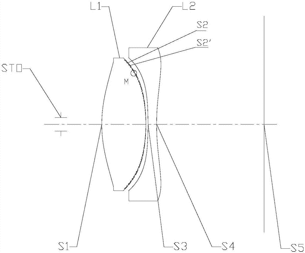
[0047] Embodiment 1 of the present application provides an eyepiece. refer to figure 1 , the eyepiece according to Embodiment 1 of the present application sequentially includes a first lens L1, a second lens L2 and a photosensitive element along the optical axis from the object side to the image side.

[0048] The parameters of each optical surface of the first lens L1, the second lens L2 and the photosensitive element are shown in Table 1 below.

[0049]

[0050]

[0051] Table 1

[0052]The aspherical high-order coefficients A4 and A6 of the first lens L1 and the second lens L2 are shown in Table 2 below.

[0053] face number A4 A6 S1 -7.2411E-06 -1.7127E-08 S2 -2.1455E-05 0.0000E+00 S3 -2.4183E-05 -1.5126E-08 S4 5.1254E-06 -2.4272E-08

[0054] Table 2

[0055] Referring to Table 1 and Table 2 and as figure 1 As shown in , the first lens L1 can have positive refractive power and its object side S1 can be convex, and the imag...

Embodiment 2

[0069] Refer to the following Figure 4 to Figure 5C Embodiment 2 of the eyepiece of the present application is described. In addition to the parameters of each lens of the eyepiece, for example, in addition to the surface type, radius of curvature, thickness, material, conic coefficient, and high-order term coefficient of each mirror surface of each lens, in this embodiment 2 and the following embodiments The eyepieces described are arranged in the same configuration as that described in Example 1. For the sake of brevity, part of the description similar to Embodiment 1 will be omitted.

[0070] Figure 4 A schematic structural view of the eyepiece according to Embodiment 2 of the present application is shown. Such as Figure 4 As shown, the eyepiece according to Embodiment 2 sequentially includes a first lens L1, a second lens L2, and a photosensitive element along the optical axis from the object side to the image side.

[0071] The parameters of each optical surface o...

Embodiment 3

[0080] Refer to the following Figure 6 to Figure 7C Embodiment 3 of the eyepiece of the present application is described. Image 6 A schematic structural view of the eyepiece according to Embodiment 3 of the present application is shown. Such as Image 6 As shown, the eyepiece according to Embodiment 3 sequentially includes a first lens L1, a second lens L2, and a photosensitive element along the optical axis from the object side to the image side.

[0081] The parameters of each optical surface of the first lens L1, the second lens L2 and the photosensitive element are shown in Table 5 below.

[0082]

[0083]

[0084] table 5

[0085] The aspherical high-order coefficients A4, A6, and A8 of the first lens L1 and the second lens L2 are shown in Table 6 below.

[0086] face number A4 A6 A8 S1 2.4212E-05 -4.4965E-08 2.3008E-11 S2 9.0284E-06 5.6179E-09 -5.2359E-11 S3 -2.9983E-05 2.7887E-08 -6.1919E-11 S4 -8.5108E-06 -1.2309E-09 ...


PUM


Abstract

The invention provides an eyepiece. The eyepiece is successively provided with a first lens with positive focal power and a convex object side and a second lens along the optical axis from the object side to the image side. The second lens has a concave image side. At least one of the object side of the first lens, the image side of the first lens, the object side of the second lens and the image side of the second lens is a Fresnel structure plane. The maximum half field angle HFOV of the eyepiece is greater than 40 degrees. According to the on-axis distance TTL from the object side of the first lens to an imaging face and the total effective focal length f of the eyepiece, 1<TTL/f<1.5. According to the total effective focal length f of the eyepiece and the on-axis distance TD from the object side of the first lens to the image side of the second lens, 2<f/TD<5. According to the effective radius DT11 of the object side of the first lens and the effective radius DT21 of the object side of the second lens, 2.7<DT11/DT21<1.

Description

technical field [0001] The present application relates to an eyepiece, and more particularly, to an eyepiece used in a head-mounted display device. The head-mounted display device may be, for example, a head-mounted virtual reality (VR) display device. The present application also relates to a display device configured with the above-mentioned eyepiece. Background technique [0002] In recent years, with the rapid development of computer technology, virtual reality (VR) has become more and more mature, and it has more and more applications in professional and consumer fields. As the core optical component of the head-mounted display device, the VR eyepiece directly affects the application and experience of the device, so it has high requirements for the imaging quality and appearance quality of the eyepiece. [0003] The head-mounted eyepiece system and the head-mounted display device proposed in the prior art can correct aberrations while obtaining a larger viewing angle,...

Claims


Application Information

Patent Timeline
Patent Type & Authority Applications(China)
IPC IPC(8): G02B25/00G02B25/04G02B27/01
CPCG02B25/001G02B25/04G02B27/0172G02B27/0025
Inventor 宋立通戴付建金银芳
Owner ZHEJIANG SUNNY OPTICAL CO LTD
Why Eureka
Try Eureka