A dynamic gas distribution instrument and gas distribution method thereof

A gas distribution instrument and dynamic technology, applied in chemical instruments and methods, mixing methods, gas and gas/vapor mixing, etc., can solve the problems affecting gas distribution accuracy, controllability and service life, easy residual gas, etc. The effect of expanding the gas flow range, simple structure and simple design

Active Publication Date: 2019-09-17
LIHE TECH (HUNAN) CO LTD
View PDF4 Cites 0 Cited by
  • Summary
  • Abstract
  • Description
  • Claims
  • Application Information

AI Technical Summary

Problems solved by technology

[0005] The first purpose of the present invention is to provide a dynamic gas distribution instrument with simple structure, improved gas distribution accuracy and self-cleaning function, so as to solve the problem that the existing gas distribution device has residual raw material gas and affects subsequent gas distribution accuracy and control. Sexuality and service life issues
[0006] The second purpose of the present invention is to provide a gas distribution method with simple structure, improved gas distribution accuracy and self-cleaning function, so as to solve the problem that the existing gas distribution method makes the raw material gas easy to remain, which in turn affects the subsequent gas distribution accuracy, Controllability and service life issues

Method used


Image

  • A dynamic gas distribution instrument and gas distribution method thereof
  • A dynamic gas distribution instrument and gas distribution method thereof

Examples


Embodiment Construction

[0031] In order to make the purpose, technical solutions and advantages of the embodiments of the present invention clearer, the technical solutions in the embodiments of the present invention will be clearly and completely described below in conjunction with the drawings in the embodiments of the present invention. Obviously, the described embodiments It is a part of embodiments of the present invention, but not all embodiments. Based on the embodiments of the present invention, all other embodiments obtained by persons of ordinary skill in the art without making creative efforts belong to the protection scope of the present invention.

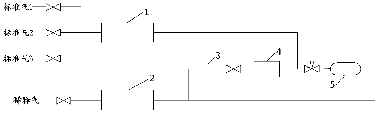
[0032] It should be noted that, in this embodiment, the standard gas may be one or more of nitrogen monoxide, carbon monoxide, carbon dioxide, methane, and propane; the diluent gas is clean air.

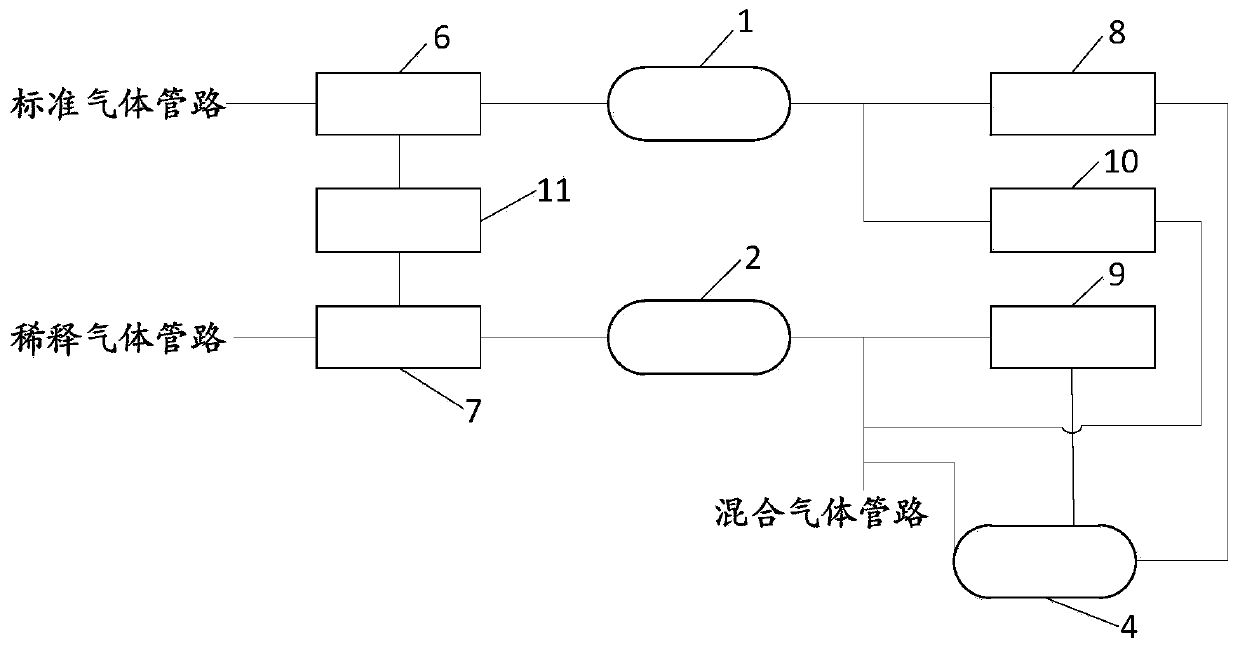
[0033] On the one hand, if figure 2 As shown, the embodiment of the present invention provides a dynamic gas distribution instrument, including a...


PUM


Abstract

The invention relates to the technical field of gas detection instruments, in particular to a dynamic gas distribution instrument and a gas distribution method thereof. The dynamic gas distribution instrument provided by the present invention includes a standard gas passage, a dilution gas passage and a mixed gas passage, the standard gas passage is provided with a first valve group and a standard gas flow controller, and the dilution gas passage is provided with a second valve group and a dilution gas passage Gas flow controller, there is a communication valve between the first valve group and the second valve group, when only diluent gas is connected, part of the diluent gas enters the mixed gas passage through the diluent gas flow controller, and the rest of the diluent gas passes through the standard gas The flow controller enters the mixed gas passage, and the gas pipeline is cleaned regularly; the standard gas passage and the dilution gas passage are respectively connected to the mixed gas passage through the standard gas flow controller and the dilution gas flow controller, and the standard gas and the dilution gas are controlled on demand. The flow rate is high, and it is connected to the mixing pipeline to configure the target gas, which is easy to operate and highly controllable.

Description

technical field [0001] The invention relates to the technical field of gas detection instruments, in particular to a dynamic gas distribution instrument and a gas distribution method thereof, in particular to a dynamic gas distribution instrument and a gas distribution method thereof with a simple structure, improved gas distribution accuracy and self-cleaning function . Background technique [0002] At present, in the field of gas detection and analysis, as the requirements for the accuracy of gas concentration detection in the field of industrial detection become more and more stringent, the requirements for the concentration of standard gases are also increased. The most commonly used method at present is to use a dilution gas flow controller and a raw gas flow controller for the dilution gas passage and the raw gas passage respectively to dilute the raw material gas in proportion to obtain the target gas. Using the above method, there are some Disadvantages: For example...

Claims


Application Information

Patent Timeline
Patent Type & Authority Patents(China)
IPC IPC(8): B01F3/02B01F15/04B01F15/00B01F23/10
CPCB01F23/10B01F35/1452B01F35/833
Inventor 彭冉郭艳刘德华王本腊严浩
Owner LIHE TECH (HUNAN) CO LTD
Why Eureka
Try Eureka