A waste gas treatment machine

A technology of waste gas treatment and gas collection chamber, which is applied in the direction of smoke and dust removal, separation of dispersed particles, chemical instruments and methods, etc. It can solve the problems of bulky waste gas treatment equipment, high cost of use, and high price, and achieve simple structure and low manufacturing cost. And the effect of low maintenance cost and easy operation

Active Publication Date: 2018-03-06
深圳科莱环保科技有限公司
View PDF4 Cites 0 Cited by
  • Summary
  • Abstract
  • Description
  • Claims
  • Application Information

AI Technical Summary

Problems solved by technology

[0002] Industrial sites often produce a large amount of industrial waste gas, such as powder waste gas particles, flue gas smoke waste gas, odorous gas, toxic and harmful gases, etc. Therefore, purification measures should be taken before being discharged into the atmosphere to make it meet the standards of waste gas discharge. Exhaust gas treatment equipment is bulky, expensive, difficult to overhaul, and expensive to use

Method used


Image

  • A waste gas treatment machine
  • A waste gas treatment machine
  • A waste gas treatment machine

Examples


Embodiment Construction

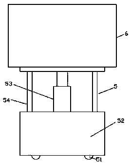
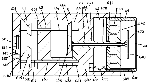
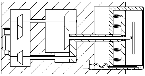
[0021] Such as Figure 1-Figure 5 As shown, an exhaust gas treatment machine of the present invention includes a hydraulic jacking device 5 and an absorption and purification structure 6 arranged on the top of the hydraulic jacking device 5 , and the inside of the right side of the absorption and purification structure 6 is provided with an accommodating groove 63 The accommodating groove 63 is slidably connected with an air collecting hood 64, the inside of the air collecting hood 64 is provided with an air collecting chamber 641, and the inside of the absorbing and purifying structure 6 on the left side of the accommodating groove 63 is provided with a transformation chamber 62, A first isolation plate 66 is provided between the transformation chamber 62 and the accommodation tank 63, and a drive chamber 61 is provided inside the absorption and purification structure 6 on the left side of the transformation chamber 62, and the drive chamber 61 and the A second isolation plat...


PUM


Abstract

The invention discloses a waste gas treatment machine. The waste gas treatment machine comprises a hydraulic jacking device and a sucking and purifying structure arranged at the top of the hydraulic jacking device. An accommodating trough is formed inside the right side surface of the sucking and purifying structure and connected with a gas collecting hood in a sliding fit mode; a gas collecting cavity is arranged inside the gas collecting hood; a conversion cavity is arranged at the position, on the left side of the accommodating trough, in the sucking and purifying structure; a first isolation board is arranged between the conversion cavity and the accommodating trough; a driving cavity is arranged at the position, on the left side of the conversion cavity, in the sucking and purifying structure; a second isolation board is arranged between the driving cavity and the conversion cavity; a first sliding groove is formed in the bottom surface of the interior of the conversion cavity; and a connecting rotating rod which extends towards the left side and the right side is connected to the inside of the first isolation board in a sliding fit mode, the right-side extending section of the connecting rotating rod extends into the accommodating trough and penetrates through the gas collecting hood to extend into the gas collecting cavity, the right-side extending tail of the connecting rotating rod is fixedly provided with a supporting board, and a first through groove extending in the left-right direction is formed inside the connecting rotating rod. The waste gas treatment machine is simple in structure and reasonable in design, the occupied space can be reduced, and the manufacturing cost and the maintaining cost are low.

Description

technical field [0001] The invention relates to the technical field of waste gas treatment, and relates to a waste gas treatment machine. Background technique [0002] Industrial sites often produce a large amount of industrial waste gas, such as powder waste gas particles, flue gas smoke waste gas, odorous gas, toxic and harmful gases, etc. Therefore, purification measures should be taken before being discharged into the atmosphere to make it meet the waste gas emission standards. Advanced waste gas treatment equipment is bulky, expensive, difficult to overhaul, and expensive to use. Contents of the invention [0003] The technical problem to be solved by the present invention is to provide an exhaust gas treatment machine, which can solve the above-mentioned problems in the prior art. [0004] The present invention is achieved through the following technical solutions: an exhaust gas treatment machine of the present invention, comprising a hydraulic jacking device and a...

Claims


Application Information

Patent Timeline
Patent Type & Authority Patents(China)
IPC IPC(8): B08B15/02B08B13/00B01D50/00
CPCB01D50/00B08B13/00B08B15/02
Inventor 叶信国
Owner 深圳科莱环保科技有限公司
Why Eureka
Try Eureka