
Adjusting Structure of Injection Rod for Die Casting Machine

A technology of adjusting structure and injection rod, applied in the field of die-casting machines, can solve problems such as troublesome installation and disassembly, achieve the effect of convenient installation and disassembly, and avoid fixed installation

Active Publication Date: 2019-02-26
BENGBU LONGHUA DIE CASTING MACHINE CO LTD
View PDF5 Cites 0 Cited by
  • Summary
  • Abstract
  • Description
  • Claims
  • Application Information

AI Technical Summary

Problems solved by technology

At present, the injection rod is directly bolted to the injection piston rod, which is very troublesome to install and disassemble.

Method used


Image

  • Adjusting Structure of Injection Rod for Die Casting Machine
  • Adjusting Structure of Injection Rod for Die Casting Machine
  • Adjusting Structure of Injection Rod for Die Casting Machine

Examples


Embodiment 1

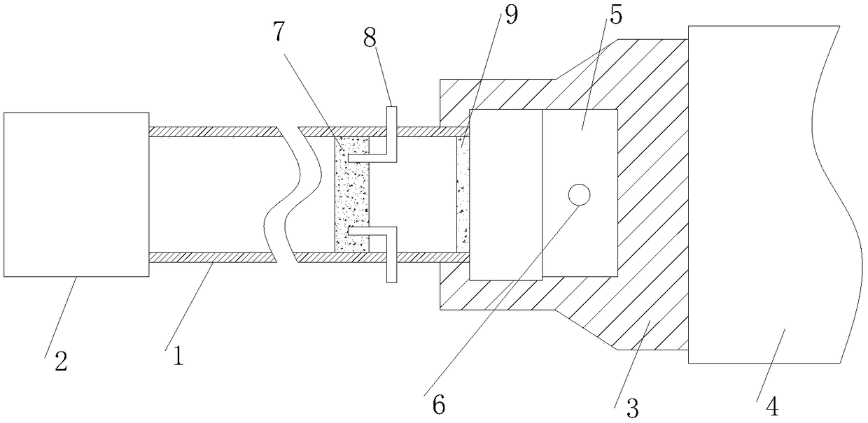
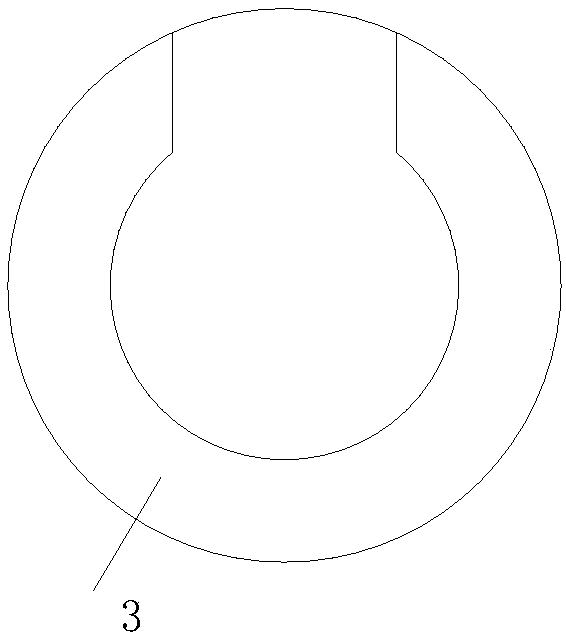
[0023] as attached figure 1 , 2 As shown, a plunger adjustment structure for a die-casting machine includes a plunger cylinder and a plunger rod 1 arranged at the front end of the plunger piston rod 4 of the plunger cylinder. A support block 3 with an opening is connected to the front end of the piston rod, and one end of the injection rod 1 is supported to the support block 3 and the other end is supported to the injection head 2 . The end of the support block 3 that is not connected to the injection piston rod has an opening, the diameter of the opening is smaller than the diameter of the abdomen, and the rear section of the injection rod has a diameter-changing shape, so that the part with a larger diameter of the injection rod sinks into the abdomen of the opening At this point, a snap-in effect is formed.

[0024] In addition, the length of the part with a larger diameter of the injection rod is less than the length of the abdomen of the opening, so that when the inject...

Embodiment 2

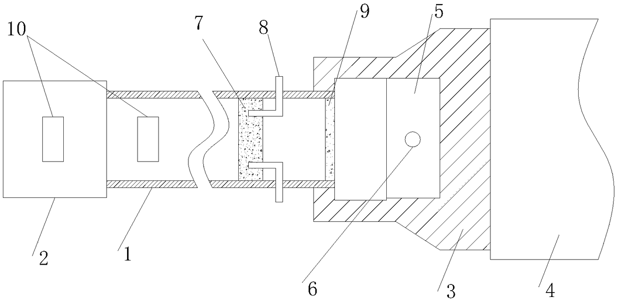
[0030] Such as image 3 As shown, as another embodiment of the present invention, a pair of grooves 10 are formed on the outer walls of the injection head 2 and the injection rod 1, and the grooves are cutouts made on the outer wall of the cylinder to facilitate the clamping of the cylinder by the wrench. The injection head and injection rod to facilitate their disassembly.


PUM


Abstract

The invention relates to the technical field of pressure casting machines, in particular to a press shooting rod adjusting structure for a pressure casting machine. The press shooting rod adjusting structure comprises a press shooting cylinder and a press shooting rod arranged at the front end of a press shooting piston rod of the press shooting cylinder, a press shooting head is connected to the front end of the press shooting rod, a supporting block with an opening is connected to the front end of the press shooting piston rod, one end of the press shooting rod is supported to a supporting block, and the other end of the press shooting rod is supported to the press shooting head. According to the press shooting rod adjusting structure, one end of the press shooting rod is directly supported into the opening of the supporting block at the front end of the press shooting piston rod, the other end of the pressure shooting rod is supported into a hole of a metal liquid cavity, and therefore during pressure shooting, the press shooting rod forwards pushes metal liquid inside the metal liquid cavity, when the pressure shooting rod retreats back, the front portion of the pressure shooting rod does not leave the metal liquid cavity and is supported into the hole of the metal liquid cavity, fixed connection between the pressure shooting rod and the press shooting piston rod is avoided, and mounting and dismounting are convenient.

Description

Technical field: [0001] The invention relates to the technical field of die-casting machines, in particular to a plunger adjustment structure for a die-casting machine. Background technique: [0002] The die-casting machine is a series of industrial casting machines that hydraulically inject molten metal into the mold under pressure to cool and form it, and obtain solid metal castings after the mold is opened. It was originally used for die-casting characters. With the advancement of science and technology and industrial production, especially with the development of industries such as automobiles, motorcycles and household appliances, die-casting technology has developed extremely rapidly in various aspects. [0003] There are many classification methods for die-casting machines, which are divided into general-purpose die-casting machines and special-purpose die-casting machines according to the scope of use; divided into small machines (≤4000kN), medium-sized machines (400...

Claims


Application Information

Patent Timeline
Patent Type & Authority Patents(China)
IPC IPC(8): B22D17/20
CPCB22D17/2015
Inventor 周文平
Owner BENGBU LONGHUA DIE CASTING MACHINE CO LTD
Learn More