Detaching and mounting methods for braking air damper of hydraulic generator
The invention relates to a technology of a hydro-generator and an installation method, which is applied in the direction of manufacturing tools, hand-held tools, etc., and can solve the problems that the brake damper cannot be carried out on the spot, there is no lifting point, and the removal and installation of the brake damper are difficult to hoist, etc. To achieve the effect of saving manpower, solving difficult hoisting, and improving the efficiency of disassembly and assembly
- Summary
- Abstract
- Description
- Claims
- Application Information
AI Technical Summary
Problems solved by technology
Method used
Image
Examples
Embodiment 1
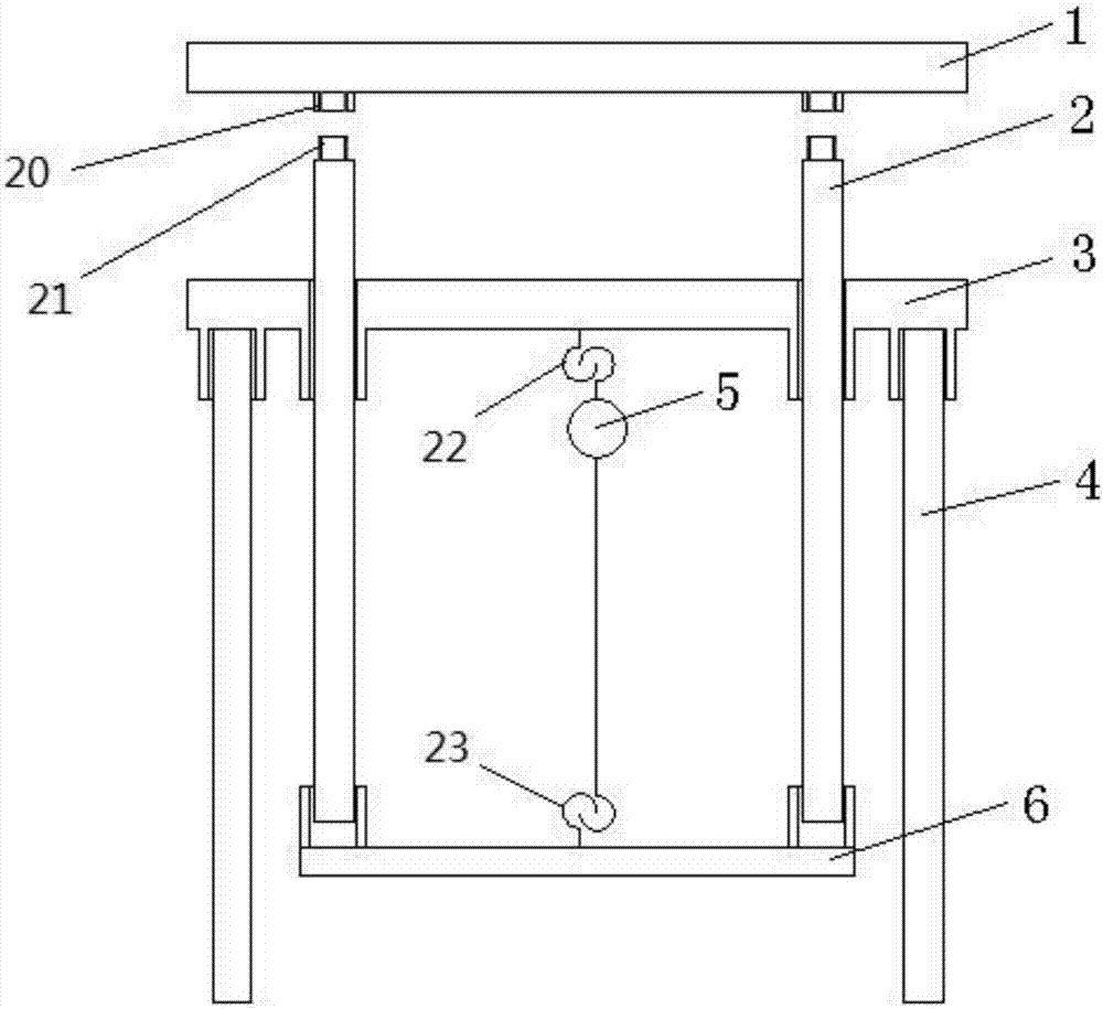
[0020] The functions realized by the hydro-generator brake damper disassembly device in this embodiment are: supporting heavy objects and driving them up and down, and its structure and shape are designed according to the special conditions of the work site.
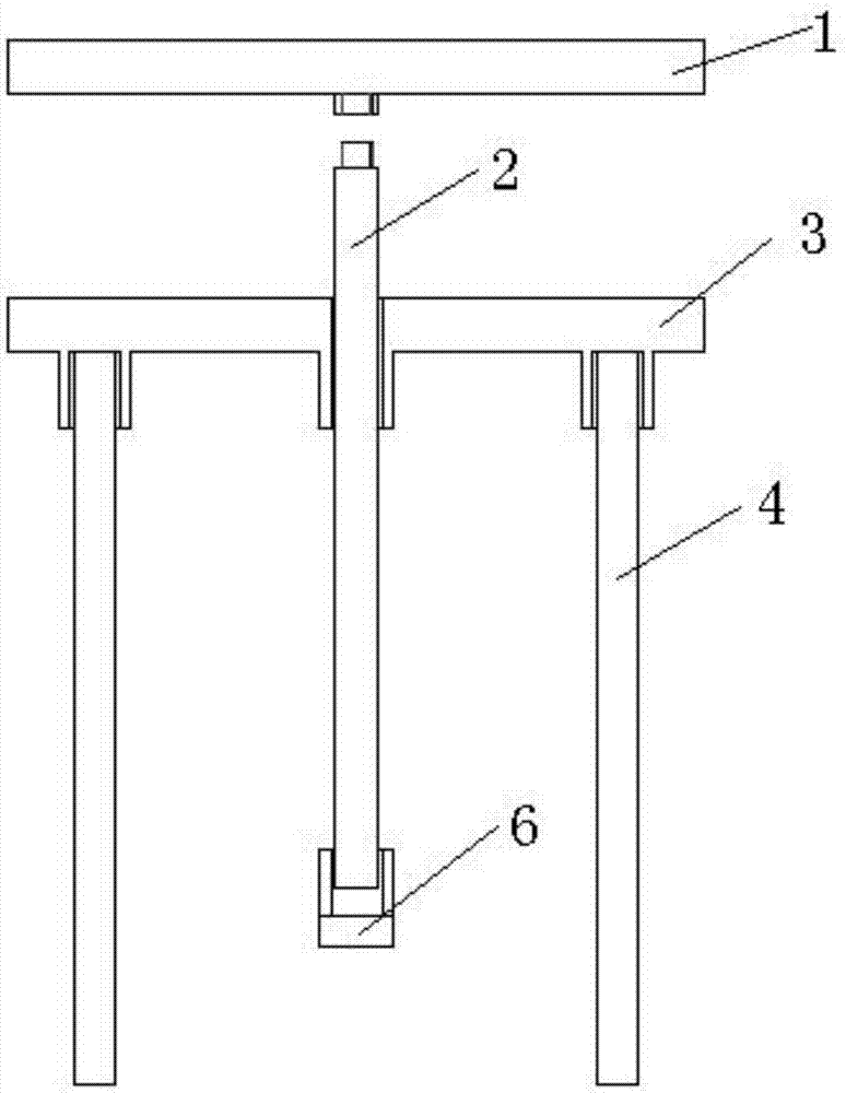
[0021] See figure 1 and figure 2 , the disassembly device mainly includes: support frame 100, lifting frame 200, top platform 1, first chain hoist 5, and second chain hoist 6, the specific division of labor is: support frame 100 plays an integral supporting role, top platform 1 Directly support the brake air brake, the lifting frame 200 is used to drive the roof 1 and the brake air brake to lift, the first chain hoist 5 is used to drive and control the lifting frame 200, and the second chain hoist 6 is used to drive the brake The damper moves.
[0022] In this embodiment, the supporting frame 100 includes a platform 3 and four supporting feet 4 . The platform 3 is square, and two through holes are arranged on the cen...
Embodiment 2
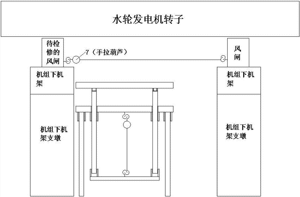
[0027] The dismantling method of the brake air brake of the hydro-generator includes the following steps: 1) Prepare the above-mentioned dismantling device; 2) Install and place the above-mentioned dismantling device; 3) Tighten the first chain hoist, the lifting frame and the top platform rise And make the top platform rise to the position consistent with the level of the air gate to be overhauled; 4) Tighten the second chain hoist, and drag the air gate to be overhauled to the top of the top platform; 5) Loosen the first chain hoist, lifting frame, The top platform and the air gate to be inspected are lowered. When the air gate to be inspected is lower than the lower frame of the unit, the lower frame is used as a lifting point to hoist the air brake to be inspected to the generator cover for inspection.
Embodiment 3
[0029] The installation method of the hydraulic generator brake damper includes the following steps: 1) Prepare the above-mentioned disassembly device; 2) Install and install the above-mentioned disassembly device; 3) Use the lower frame as the lifting point, and it will be completed on the generator cover Hoist the overhauled air gate to the top platform; 4) Tighten the first hand chain block, the lifting frame, the top platform and the overhauled air gate rise together, so that the overhauled air gate rises to the height of the original installation position; 5) The second chain hoist is connected between the overhauled damper and another fixed damper, tighten the second chain hoist, drag the overhauled damper back to the original installation position, and then tighten it The bolts complete the installation.
PUM
 Abstract
Description
Claims
Application Information
 - R&D
- Intellectual Property
- Life Sciences
- Materials
- Tech Scout
- Unparalleled Data Quality
- Higher Quality Content
- 60% Fewer Hallucinations
Browse by: Latest US Patents, China's latest patents, Technical Efficacy Thesaurus, Application Domain, Technology Topic, Popular Technical Reports.
© 2025 PatSnap. All rights reserved.Legal|Privacy policy|Modern Slavery Act Transparency Statement|Sitemap|About US| Contact US: help@patsnap.com


