Eureka AIR delivers breakthrough ideas for toughest innovation challenges, trusted by R&D personnel around the world.

Drainpipe-shaped antenna structure

An antenna structure and antenna technology, which is applied in the direction of antenna, antenna parts, radiation element structure, etc., can solve the problems of antenna drop, drainage pipe antenna installation and operation difficulty, etc., so as to avoid antenna drop, reduce difficulty, and improve The effect of application range

Pending Publication Date: 2018-09-28
TONGYU COMM INC
View PDF5 Cites 0 Cited by
  • Summary
  • Abstract
  • Description
  • Claims
  • Application Information

AI Technical Summary

Problems solved by technology

[0005] The purpose of the present invention is to solve the problem that the installation and operation of the drainpipe antenna in the prior art is difficult, and the antenna will fall if the installation is not firm, and to provide a drainpipe-shaped antenna structure

Method used


Image

  • Drainpipe-shaped antenna structure
  • Drainpipe-shaped antenna structure
  • Drainpipe-shaped antenna structure

Examples


Embodiment Construction

[0023] As shown in the figure, the specific implementation method is as follows:

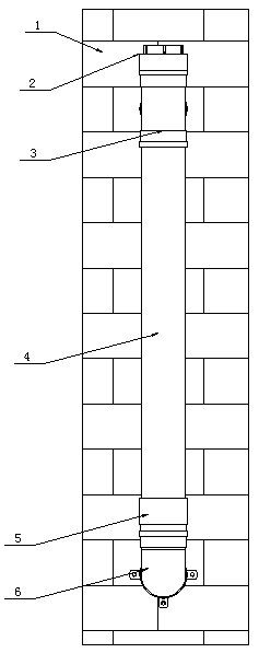
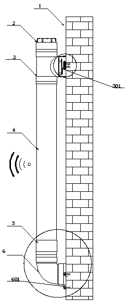
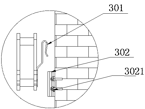
[0024] A drainage pipe-shaped antenna structure, including a water pipe-shaped antenna body 4, the top of the antenna body 4 is connected with a tee joint 3, and the tee joint 3 adopts an equal-diameter tee, or a non-equal-diameter tee , but it is not convenient to use the equal diameter tee in the installation process and later use, and the appearance of the equal diameter tee is better. On the wall 1, a hook assembly for hooking the antenna body 4 on the outer wall 1 is arranged inside the end of the tee joint 3 close to the outer wall 1, and the other end of the tee joint 3 is provided with an inspection port 2 for overhauling the antenna body. The bottom of the body 4 is connected with a connection cover 5, and the end of the connection cover 5 away from the antenna body 4 is fixed on the outer wall 1 for installing the antenna structure through an elbow pre-embedded installation part 6, and...


PUM


Abstract

The invention relates to a drainpipe-shaped antenna structure. The drainpipe-shaped antenna structure comprises a drainpipe-shaped antenna body, wherein the top portion of the antenna body is connected with a three-way connector, one end of the three-way connector perpendicular to the pipe diameter direction is buckled on an outer wall used for mounting an antenna structure, one end of the three-way connector close to the outer wall is internally provided with a hook assembly used for hooking the antenna body on the outer wall, a bottom portion of the antenna body is connected with a connection cover, one end of the connection cover away from the antenna body is fixed through an elbow pre-embedded mounting member on the outer wall used for mounting the antenna structure, and the antenna structure is fixed through cooperation of the outer wall through the hook assembly and the elbow pre-embedded mounting member. The drainpipe-shaped antenna structure is advantaged in that the hitching supporting effect can be realized through cooperation of a first suspension member and a second suspension member, a problem of difficulty of suspension mounting of the drainpipe antenna on the outer wall is solved, a problem of drop of the antenna because of infirm mounting can be avoided through hitching, and a safety coefficient of mounting construction of the drainpipe-shaped antenna on the outer wall can be improved.

Description

technical field [0001] The invention relates to the field of beautifying antenna structure design, in particular to an antenna mounted on an outer wall. Background technique [0002] With the development of the mobile communication industry, wireless communication products are increasingly appearing in people's lives, and a large number of antenna equipment for transmitting and receiving wireless signals appear in every corner of the city and the countryside. The existing antenna equipment needs to be installed with the help of complex It is extremely inconvenient to install with auxiliary installation equipment such as cranes, slings, and ladders, and may affect the safety of installers. In addition, people's health awareness of electromagnetic radiation is getting stronger and stronger, and the shape of these antenna devices Different antenna structures with different shapes will not only cause visual pollution to people, but also may cause people’s fear of electromagnetic...

Claims


Application Information

Patent Timeline
Patent Type & Authority Applications(China)
IPC IPC(8): H01Q1/12H01Q1/36
CPCH01Q1/1221H01Q1/36
Inventor 尹江南屈亮袁广弋杨浩斌张毅张理栋
Owner TONGYU COMM INC
Why Eureka
Eureka Blog
Learn More