A method of using an attached lifting and transporting device for demolishing concrete support beams

A transportation device, concrete technology, applied in transportation and packaging, walking bridge cranes, cranes, etc., to achieve the effect of promoting production progress, flexible lifting and transportation, and simple structure

Active Publication Date: 2021-10-01
CHINA TIESIJU CIVIL ENG GRP CO LTD +1
View PDF5 Cites 0 Cited by
  • Summary
  • Abstract
  • Description
  • Claims
  • Application Information

AI Technical Summary

Problems solved by technology

[0003] The invention provides a method for using an attached lifting and transporting device for dismantling concrete support beams, so as to solve the working radius of the hoisting machine in the prior art that can only use tower cranes and other hoisting machines for lifting, transporting, and dismantling structures The problem of external lifting and transportation, and at the same time relieve the pressure of lifting machinery hoisting, so as to promote the production progress

Method used


Image

  • A method of using an attached lifting and transporting device for demolishing concrete support beams
  • A method of using an attached lifting and transporting device for demolishing concrete support beams
  • A method of using an attached lifting and transporting device for demolishing concrete support beams

Examples


Embodiment 1

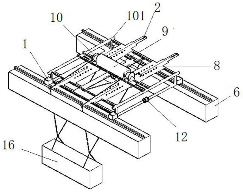
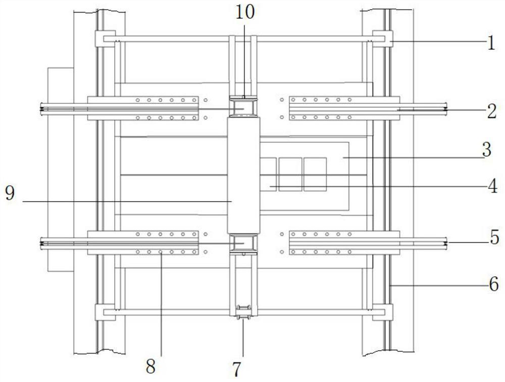
[0037] An attached lifting and transporting device for demolishing concrete support beams, including a trolley system and a lifting system, see figure 1 , the trolley system includes a trolley 101 arranged on the running track 6, and the trolley 101 is set as a structure including upper and lower layers of "mesh"-shaped frames, and the "mesh"-shaped frames are all composed of beam connections, and the upper 1. The "mesh"-shaped frames on the lower two floors are all connected by vertical connecting beams at the four corners; see figure 2 , the middle part of the "mesh"-shaped frame of the upper layer is connected with the upper steel plate on the two vertical connecting beams perpendicular to the direction of the running track 6, and the two ends of the upper steel plate are respectively symmetrically provided with two rows of first bolt holes, each The number of the first bolt holes in each row is at least two, and the number is evenly distributed. The four cantilever beams ...

Embodiment 2

[0043] An attached lifting and transporting device for removing concrete support beams. On the basis of Embodiment 1, further, the two sides of the trolley system are respectively provided with support removal devices 17, and the support removal devices 17 are provided with concrete support beams. Block 16, the two ends of the concrete support beam block 16 are provided with reserved hoisting holes.

[0044] Furthermore, the ends of the hoisting rope 15 and the external force pulling rope 7 are respectively provided with matching locks.

[0045] Furthermore, the cantilever beam 2 is formed by welding one beam steel plate and two beam steel bars.

[0046] Furthermore, two rows of second bolt holes are provided on the beam steel plate, and the number of the second bolt holes in each row is at least two, and the number of the second bolt holes is evenly distributed.

[0047] Furthermore, the four cantilever beams 2 are evenly distributed into two groups, and are symmetrically in...

Embodiment 3

[0050] Embodiment 1 or embodiment 2 described attached demolition concrete support beams use the method of lifting, transportation device, comprise the following steps,

[0051] The first step is to lay and fix the running track 6 according to the needs of the scope of work;

[0052] In the second step, the trolley 101 is installed on the running track 6, and the cantilever distance of the cantilever beam 2 is adjusted by adjusting the bolts of the cantilever beam 2 according to the maximum load of lifting;

[0053] The third step is to select the counterweight 4 according to the maximum lifting load, and place the counterweight 4 on the counterweight pallet 3;

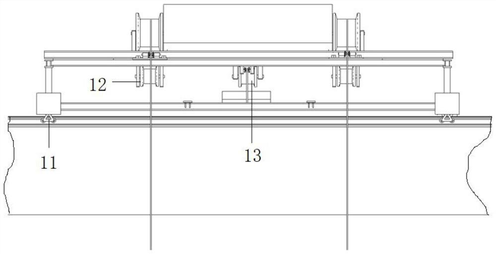
[0054] In the fourth step, the hoisting rope 15 and the external force traction rope 7 are drawn out from the hoisting hoist 10 and the traction hoist 12 respectively, and are extended downward through the guide wheel 5 on the hoisting side;

[0055] In the fifth step, the trolley 101 moves to the top of the lifting ...


PUM


Abstract

The invention discloses a method for using an attached lifting and transportation device for demolishing concrete support beams. The lifting and transportation device includes a trolley system and a lifting system. The trolley system includes a trolley arranged on a running track, and the trolley includes an upper, The structure of the "mesh"-shaped frame on the lower two floors is equipped with a counterweight tray on the lower steel plate. , speed-limiting braking device; traction winches with the same power and synchronous operation are respectively fixed in the middle of the running tracks on both sides of the foundation pit, and the counterweight adjustment hoist, cantilever beam, traction hoist, and two identical power and synchronous operation The lifting winch constitutes a lifting system; effectively solves the problem of dismantling and lifting vertical multi-layer support beams, and can be used for dismantling, lifting and transportation of super-sized and large-section concrete support beams, relieves the pressure of lifting operations, and ensures construction progress.

Description

technical field [0001] The invention belongs to the technical field of building construction, and in particular relates to a method for using an attached lifting and transporting device for demolishing concrete support beams. Background technique [0002] Most deep foundation pits are designed in the form of concrete support beams. However, in the construction of super-large deep foundation pits and large-section concrete support beams, the previous lifting machinery such as tower cranes cannot meet the construction requirements. , The transportation method has the following disadvantages: ①The dismantling of super-large deep foundation pits and super-large cross-section support beams will cause secondary transportation after the demolition of concrete support beams due to the limited radius of existing mechanical operations and the limitation of lifting load at the end. Increase labor and machinery costs. Therefore it is conceived to provide a lifting and transportation de...

Claims


Application Information

Patent Timeline
Patent Type & Authority Patents(China)
IPC IPC(8): B66C11/04B66C11/20B66C17/04E04G23/08
CPCB66C11/04B66C11/20B66C17/04E04G23/08
Inventor 尹钱超李锐超黄刚夏正平纪鹏洋雷鹏汪际周自强
Owner CHINA TIESIJU CIVIL ENG GRP CO LTD
Why Eureka
Try Eureka