Road construction buffer fence

A road construction and fencing technology, which is applied in the field of road construction buffer fences, can solve the problems of not being able to effectively prevent out-of-control vehicles rushing to the construction site, poor buffering effect, etc., and achieve the effects of convenient replacement, safety protection, and reduced damage

Inactive Publication Date: 2017-08-18
成都市德容建筑劳务有限公司
View PDF5 Cites 7 Cited by
  • Summary
  • Abstract
  • Description
  • Claims
  • Application Information

AI Technical Summary

Problems solved by technology

[0004] The purpose of the present invention is to provide a road construction buffer fence, which solves the problem that the existing road construction fence has poor buffering effect and cannot effectively prevent out-of-control vehicles from rushing to the construction site

Method used


Image

  • Road construction buffer fence
  • Road construction buffer fence

Examples


specific Embodiment 1

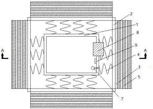
[0025] figure 1 , figure 2 Shows a road construction buffer fence, including an inner fence 1, an outer buffer fence 2 and a slope buffer part 3. The inner fence 1 is fixed on the ground at the periphery of the construction area, and the outer wall of the inner fence 1 is set perpendicular to the inner The spring 4 on the outer wall of the fence. The other end of the spring 4 is connected with an outer buffer plate 2 parallel to the outer wall of the inner fence. The bottom of each outer buffer plate is provided with a slope buffer part 3, and the slope of the slope buffer part 3 is inclined toward The exterior slopes downward.

[0026] When a car runs out of control and rushes to the road construction site, it will first contact the slope buffer 3. Since the slope buffer 3 is inclined, the out-of-control car will be slowed down due to upward work when it touches the slope buffer 3. At this time, if the out-of-control car continues to move forward, it will hit the outer buffer ...

specific Embodiment 2

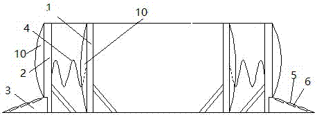
[0028] In this embodiment, a deceleration belt 5 is added on the basis of specific embodiment 1. The slope of the ramp buffer 3 is provided with a convex deceleration belt 5, and there are more than two deceleration belts 5 on each slope.

[0029] The protruding speed bumps 5 are provided on the slope of the ramp buffer 3 to further slow down the out-of-control vehicle, and there are two or more speed bumps 5 on each slope to make the ramp buffer 3 have better deceleration effect.

specific Embodiment 3

[0031] This embodiment further describes the structure of the ramp buffer 3 on the basis of the specific embodiment 2. The slope of the ramp buffer 3 is also provided with a deceleration belt groove 6, and the bottom of the deceleration belt groove 6 is provided with a fixed In the hole position, the bottom of the deceleration belt 5 is provided with a convex part that matches the fixed hole position, and the deceleration belt 5 is placed in the deceleration belt groove 6.

[0032] A speed bump groove 6 is provided on the slope of the slope buffer 3, so that it is more convenient to replace the old speed bump 5, and secondly, the speed bump 5 can be adjusted according to the different conditions of the road construction site. The road construction site is located in the traffic flow When the road is larger and the speed is faster, replace it with a speed bump with a better deceleration effect. When the road construction site is on a relatively remote road with low traffic volume a...


PUM


Abstract

The invention discloses a road construction buffer fence. The road construction buffer fence comprises an inner fence, outer buffer fence plates and ramp buffer parts, wherein the inner fence is fixedly arranged on the peripheral floor of a construction area; springs are arranged at the outer wall of the inner fence and are perpendicular to the outer wall of the inner fence; the other end of each spring is connected with the corresponding outer buffer plate which is parallel with the outer wall of the inner fence; the bottom part of each outer buffer plate is provided with the corresponding ramp buffer part; a ramp of each ramp buffer part is inclined downwards to the exterior. The road construction buffer fence solves the problems of poor buffer effect, and failure to effectively block the out-of-control vehicles from rushing into the construction site in the existing road construction fence.

Description

Technical field [0001] The invention relates to the field of building construction equipment, in particular to a road construction buffer fence. Background technique [0002] Road construction fences are an important task of road construction. Since many construction sites are located on roads where vehicles are constantly flowing during road construction, the road construction fences are set up to ensure the safety of construction workers and prevent dust reduction. The effect of noise effectively reduces the impact of construction on the surrounding environment. [0003] However, the existing road construction fences are usually made of single-layer metal plates. If the vehicle accidentally runs out of control and crashes into the road construction site, the existing road construction fences play a small role and cannot be effective. To prevent out-of-control vehicles from rushing to the construction site, the safety of construction workers on the road construction site cannot ...

Claims


Application Information

Patent Timeline
Patent Type & Authority Applications(China)
IPC IPC(8): E01C23/00E01F15/14
CPCE01C23/00E01F15/145
Inventor 曾晓予
Owner 成都市德容建筑劳务有限公司
Why Eureka
Try Eureka