
Breakwater structure

A technology for breakwaters and embankments, applied in the direction of breakwaters, jetties, embankments, etc., can solve problems such as blockage of wave dissipation holes, difficulty in cleaning, and poor offsetting ability, and achieve the effects of reducing wave impact, facilitating construction operations, and ensuring stability

Inactive Publication Date: 2017-08-18
ZHEJIANG UNIV OF WATER RESOURCES & ELECTRIC POWER
View PDF4 Cites 8 Cited by
  • Summary
  • Abstract
  • Description
  • Claims
  • Application Information

AI Technical Summary

Problems solved by technology

[0003] 1. The construction of the breakwater remains unchanged, and the ability to offset the impact of waves is poor. Under large waves, it is easy to cause the movement and dislocation of the wave-dissipating plates installed on the breakwater, and the stability of long-term use will gradually deteriorate.
[0004] 2. Garbage in Hanoi and the sea cannot be recycled and cleaned. The garbage will stay in the water with the advance and retreat of the waves. In order to avoid the stress concentration on the scene under the impact of waves, wave dissipation holes are generally set on the wave dissipation plate, and the garbage in the river floats Objects, etc. will easily lead to blockage of the wave dissipation hole, affecting the normal operation of the wave dissipation hole, and it is not easy to clean
[0005] 3. The noise pollution caused by wave impact is large

Method used


Image

  • Breakwater structure
  • Breakwater structure
  • Breakwater structure

Examples


Embodiment Construction

[0029] The present invention will be further described in conjunction with the accompanying drawings and specific embodiments. It should be understood that these examples are only used to illustrate the present invention and are not intended to limit the scope of the present invention. In addition, it should be understood that after reading the content taught by the present invention, those skilled in the art may make various changes or modifications to the present invention, and these equivalent forms also fall within the scope defined in the present application.

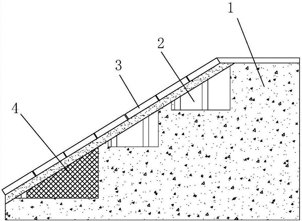
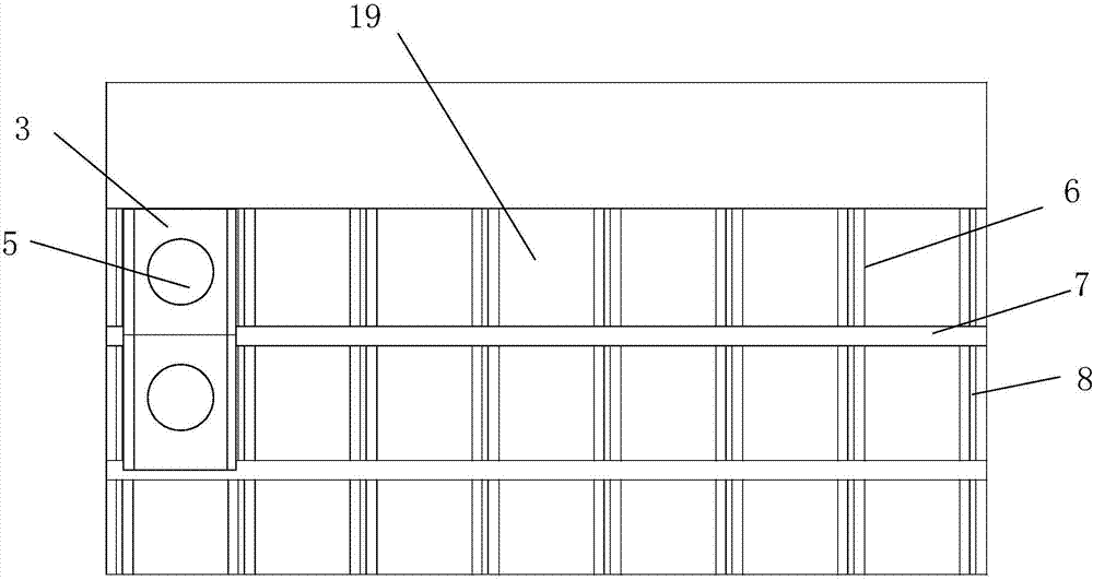
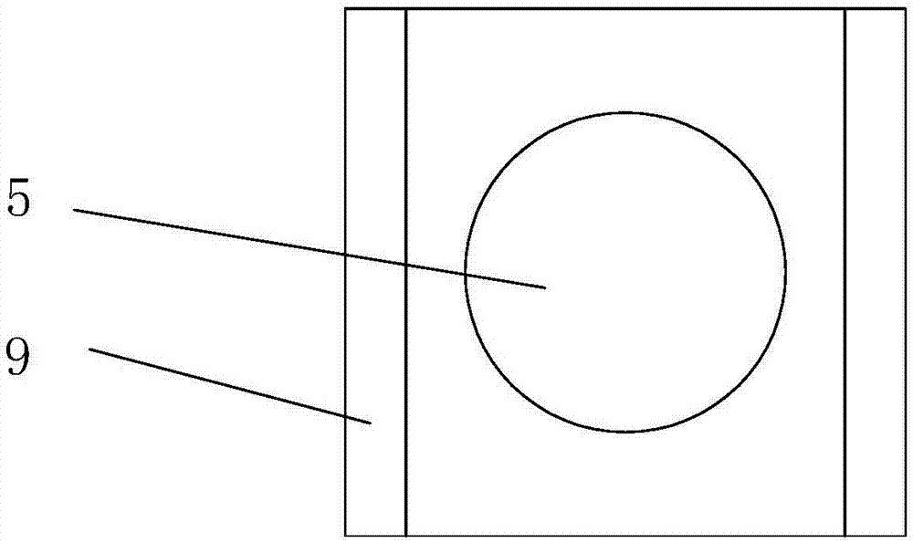
[0030] as attached Figure 1~6 As shown, a breakwater structure includes a dike body with a slope facing the sea side. The dike body 1 opens a cavity 19 from the upper slope to the inner side of the dike body. port 2, the flow port 2 communicates with the interior of the cavity 19, and several horizontal concrete walls 7 and vertical concrete walls 6 are arranged in the cavity 19, and the horizontal concrete walls...


PUM


Abstract

The invention provides a breakwater structure which comprises a breakwater body. The two sides of the breakwater body are each provided with multiple through through-flow openings. The through-flow openings communicate with a cavity. Multiple transverse concrete walls and vertical concrete walls are arranged in the cavity. A rectangular grid structure is formed by the transverse concrete walls and the vertical concrete walls. A flow guide channel communicating with the corresponding through-flow opening is arranged in each grid. Multiple wave dissipation plates are mounted on the upper inclined face of the breakwater body. The wave dissipation plates are arranged between the grids formed by the transverse concrete walls and the vertical concrete walls. A wave dissipation hole used for wave dissipation is formed in each wave dissipation plate. After the wave dissipation plates are fixed to the transverse concrete walls and the vertical concrete walls, the wave dissipation holes of the wave dissipation plates communicate with the flow guide channels below the wave dissipation plates. The through-flow openings of the two sides of the breakwater body are provided with filter screens. The breakwater structure is convenient to construct and has a good dissipation capacity on waves, garbage floating objects in rivers and seas can be subjected to recovery cleaning, and the waves are prevented from flowing back into the rivers and the seas again.

Description

technical field [0001] The invention mainly relates to the technical field of breakwaters, in particular to a breakwater structure applicable to river banks, coasts or ports and capable of effectively filtering garbage in water. Background technique [0002] Breakwaters are water structures built to block the impact of waves, maintain the harbor basin, maintain a stable water surface to protect the port from weather, and to facilitate safe berthing and operation of ships. Existing breakwater structures can generally be divided into two types: heavy and light. Among heavy breakwaters, there are slope dikes. When waves meet with slope dikes, they will undergo significant changes and break on the slopes, bringing local concentrated dynamic water pressure and bottom currents to the slopes. There is also upward counter pressure on the underwater slope. Therefore, natural large stones, artificial concrete blocks or special-shaped blocks are often used for the outer slope of the e...

Claims


Application Information

Patent Timeline
Patent Type & Authority Applications(China)
IPC IPC(8): E02B3/06
CPCE02B3/066
Inventor 孙仲健陈芃
Owner ZHEJIANG UNIV OF WATER RESOURCES & ELECTRIC POWER
Learn More