
Locking method for valve lift device

A technology of valve lift and setting value, which is applied to valve devices, engine components, machines/engines, etc., to achieve the effects of reducing fuel consumption, reducing noise and prolonging service life

Inactive Publication Date: 2017-08-18
庄铭钦
View PDF5 Cites 0 Cited by
  • Summary
  • Abstract
  • Description
  • Claims
  • Application Information

AI Technical Summary

Problems solved by technology

[0006] The invention proposes a valve adjustment system and method, which solves the problem of the spring pressure in the same valve with different engine speeds in the prior art

Method used


Image

  • Locking method for valve lift device
  • Locking method for valve lift device
  • Locking method for valve lift device

Examples


Embodiment Construction

[0036] The following will clearly and completely describe the technical solutions in the embodiments of the present invention with reference to the accompanying drawings in the embodiments of the present invention. Obviously, the described embodiments are only some, not all, embodiments of the present invention. Based on the embodiments of the present invention, all other embodiments obtained by persons of ordinary skill in the art without creative efforts fall within the protection scope of the present invention.

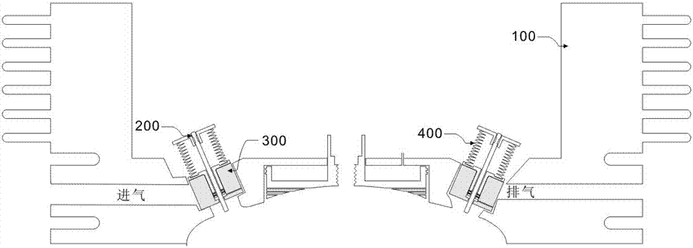
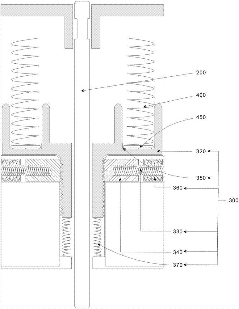
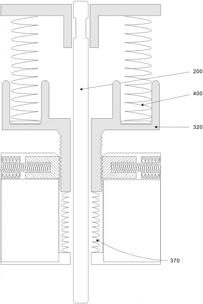
[0037] A method for controlling an engine valve innerspring comprising adjusting pressure to the valve innerspring 400 based on engine speed, adjusting the pressure of the valve innerspring 400 including adjusting an electrical control coupled to a solenoid 360 . The valve inner spring 400 is a spring that is sleeved in an outer spring among the two return springs of the valve 200 .

[0038] Among them, such as figure 1 , 2 , 3, the power supply controls the lift...


PUM


Abstract

The invention provides a locking method for a valve lift device. Within the first time when the rotation speed of an engine reaches the set value, the movement of a positioning plate is achieved through adjustment. When the rotation speed of the engine is increased and exceeds the set value or is reduced to the set value, electromagnetism work is achieved through adjustment. When the set value is exceeded, a piston ascends to the terminal point under the action of a pressure spring. At the terminal point, an electromagnetism power source is controlled to be turned off, a positioning spring pushes a positioning plate out so that the positioning plate can be combined with the piston, and the piston is positioned at the terminal position. When the set value is reached through lowering, a valve press disc downwards presses an inner spring, meanwhile, the piston is subjected to pressure of the inner spring, the pressure spring is pushed back to the original position, and the piston descends to the initial point. At the initial point, the electromagnetism power source is controlled to be turned off, the positioning spring pushes the positioning plate out so that the positioning plate and the piston can be combined, and the piston is positioned at the initial point position.

Description

technical field [0001] The invention relates to an internal combustion engine, in particular to a method for adjusting and locking the pressure of a valve inner spring according to the engine speed. Background technique [0002] The valve spring of the engine is the only part that guarantees the valve reset. If the valve spring force is too large, it will seriously damage the wear of the parts of the valve train. If the valve spring force is too small, the valve reset will lag behind, causing the valve and the power piston to collide. [0003] The return force of the valve spring is set according to the maximum speed of the engine to ensure the high-speed operation of the engine. However, the pressure of the valve spring at the highest speed is relatively large, which will inevitably affect the torque of the engine at low speeds. [0004] In order to achieve the reset speed of the valve in some high-speed engines, the valve spring adopts a double spring design, one inner s...

Claims


Application Information

Patent Timeline
Patent Type & Authority Applications(China)
IPC IPC(8): F01L13/00
CPCF01L13/0015
Inventor 庄铭钦
Owner 庄铭钦
Learn More