Piston pump exhaust structure

A piston pump and piston technology, which is applied to pump components, variable displacement pump components, and components of pumping devices for elastic fluids, etc., can solve the problems of unsmooth liquid discharge, affecting the use effect, etc. , use the effect of good effect

Pending Publication Date: 2017-08-18
江西万年芯微电子有限公司
View PDF0 Cites 0 Cited by
  • Summary
  • Abstract
  • Description
  • Claims
  • Application Information

AI Technical Summary

Problems solved by technology

The liquid discharge structure of the prior art will contain gas in the discharge liquid, which affects its use effect and the liquid discharge is not smooth

Method used


Image

  • Piston pump exhaust structure
  • Piston pump exhaust structure

Examples


Embodiment Construction

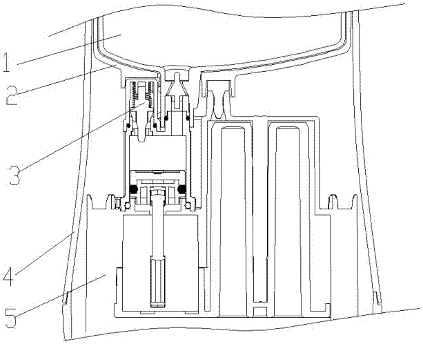
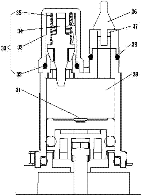
[0017] Referring to the accompanying drawings, a piston pump exhaust structure of the present invention, the piston pump includes a hydraulic cylinder 39, a piston 31 and a liquid inlet check valve 36, the liquid inlet check valve 36 is connected to the hydraulic cylinder 39, and is characterized in that: It includes a liquid outlet check valve 30 communicating with a hydraulic cylinder 39, the liquid outlet check valve 30 includes a liquid outlet valve seat 33, a sealing ring 32, a needle valve 34 and a spring 35 installed in the liquid outlet valve seat 33, The sealing ring 32 is installed between the liquid outlet valve seat 33 and the needle valve 34, a spring 35 is arranged above the needle valve 34, and there is a liquid outlet (not shown in the figure) above the liquid outlet valve seat 33.

[0018] see figure 1 , in an embodiment of the present invention, the piston pump 3 is installed on the soap dispenser, and the liquid inlet check valve 36 communicates with the liq...


PUM


Abstract

A piston pump exhaust structure, the piston pump includes a hydraulic cylinder, a piston and a liquid inlet check valve, the liquid inlet check valve is connected with the hydraulic cylinder, and also includes a liquid outlet check valve communicated with the hydraulic cylinder, the The liquid outlet check valve includes a liquid outlet valve seat and a sealing ring installed in the liquid outlet valve seat, a needle valve and a spring. The sealing ring is installed between the liquid outlet valve seat and the needle valve. There is a liquid outlet above the valve seat. Its advantage is that there is no gas in the liquid, the liquid is smooth, and the use effect is good.

Description

technical field [0001] The invention relates to an elastic fluid pump, relates to the setting of a valve, in particular to a piston pump exhaust structure. Background technique [0002] A liquid tank is installed in the soap dispenser, the liquid tank is connected to the liquid inlet check valve, the liquid inlet check valve is connected to the liquid inlet to the hydraulic cylinder, the hydraulic cylinder is connected to the outlet, the outlet is connected to the liquid outlet check valve, and the liquid outlet check valve is controlled by Driven by the piston of the hydraulic cylinder, the soap liquid in the hydraulic cylinder is discharged through the liquid outlet of the liquid outlet check valve. The liquid discharge structure of the prior art will contain gas in the discharge liquid, which affects its use effect and the liquid discharge is not smooth. Contents of the invention [0003] Aiming at the shortcomings of the prior art, the object of the present invention ...

Claims


Application Information

Patent Timeline
Patent Type & Authority Applications(China)
IPC IPC(8): F04B53/06F04B53/10
CPCF04B53/06F04B53/10
Inventor 陈维
Owner 江西万年芯微电子有限公司
Why Eureka
Try Eureka