Multifunctional container

A multifunctional container technology, applied in the field of packaging containers, can solve the problems of inconvenient use, unsafe sanitation, flying insects, etc., and achieve the effect of convenient pouring and smooth liquid discharge

Active Publication Date: 2022-04-05
李红彪
View PDF7 Cites 0 Cited by
  • Summary
  • Abstract
  • Description
  • Claims
  • Application Information

AI Technical Summary

Problems solved by technology

In the prior art, there is an inner cover / plug that is directly made of silica gel. However, with this structure, the inner cover / plug needs to be removed during use. During the process of removing the inner cover / plug, after opening and using There is a problem of poor sealing performance
[0003] At the same time, the existing seals for sealing containers need to be damaged or torn when the container is used, causing the seal to lose its sealing function; The cavity is sealed, which causes inconvenience to the user and the sealing is not timely, which affects the drinking safety and service life of the substance filled in the inner cavity of the container
[0004] At the same time, existing containers require the user to manually close the mouth of the container, which causes dust and flying insects to enter the inner cavity of the container when the user forgets or does not close the mouth of the container in time, which is unsafe and hygienic
[0005] At the same time, the existing containers are always more laborious or difficult to take the contents of the container when taking them, which causes inconvenience for users.

Method used


Image

  • Multifunctional container
  • Multifunctional container
  • Multifunctional container

Examples


Embodiment 1

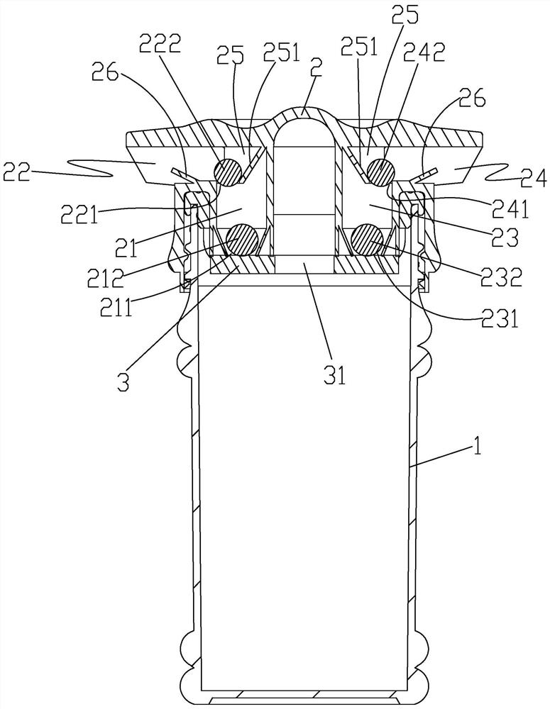
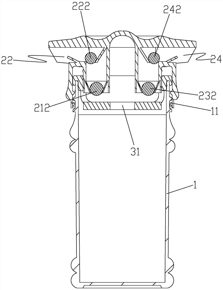
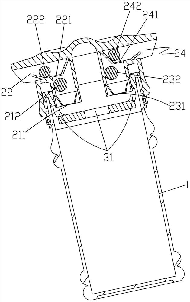
[0044] Such as Figure 1-3 As shown, a multifunctional container of the present invention includes a container body 1 and an upper cover 2 connected to the mouth of the container body 1, and the upper cover 2 is provided with a left liquid outlet control chamber 21 and a right liquid outlet control chamber 23. The left liquid outlet control chamber 21 has a first liquid outlet 211 communicating with the inner cavity of the container body 1, and the left liquid outlet control chamber 21 is provided with a first liquid outlet 211 for opening or blocking the first liquid outlet 211. A sealing ball 212, the upper cover 2 is provided with a left liquid outlet channel 22 that communicates the left liquid outlet control chamber 21 with the outside, and the inner port of the left liquid outlet channel 22 is formed with a port that communicates with the left liquid outlet control chamber 21 The second liquid outlet 221, the left liquid outlet channel 22 is provided with a second sealin...

Embodiment 2、3

[0054] Such as Figure 4-7 As shown, a multifunctional container of the present invention includes a container body 1 and an upper cover 2 connected to the mouth of the container body 1, the upper cover 2 is provided with a left liquid outlet control chamber 21 and a right liquid outlet control chamber 23, The left liquid outlet control chamber 21 has a first liquid outlet 211 communicating with the inner cavity of the container body 1, and the left liquid outlet control chamber 21 is provided with a first seal for opening or blocking the first liquid outlet 211. Ball 212, the upper cover 2 is provided with a left liquid outlet window 27 that communicates the left liquid outlet control chamber 21 with the outside, and the inner side wall of the upper cover 2 is rotatably connected with the left liquid outlet window 27 and the left liquid outlet window 27. The left liquid outlet nozzle 271 connected or isolated from the control chamber 21, the right liquid outlet control chambe...

Embodiment 4

[0065] Such as Figure 8 , 9 As shown, a multifunctional container of the present invention includes a container body 1 and an upper cover 2 connected to the mouth of the container body 1, and the upper cover 2 is respectively provided with a left liquid outlet window that communicates with the inner cavity of the container body 1 27 and the right liquid outlet window 28, the inner side wall of the upper cover 2 is rotatably connected with the left liquid outlet nozzle 271 which can connect or isolate the left liquid outlet window 27 and the inner cavity of the container body 1, and the left liquid outlet nozzle 271 The end is provided with a left counterweight 272 that can rotate the left liquid outlet nozzle 271 to the position of blocking the left liquid outlet window 27 when the container body 1 is placed upright. The liquid window 28 communicates with or isolates the right liquid nozzle 281 from the inner cavity of the container body 1. The inner end of the right liquid ...


PUM


Abstract

A left liquid outlet nozzle capable of communicating or isolating a left liquid outlet window from an inner cavity of a container body is rotatably connected to the inner side wall of an upper cover, and a left balancing weight capable of rotating the left liquid outlet nozzle to block the left liquid outlet window when the container body is vertically placed is arranged at the inner end of the left liquid outlet nozzle; the inner side wall of the upper cover is further rotationally connected with a right liquid outlet nozzle capable of communicating or isolating the right liquid outlet window and the inner cavity of the container body, and the inner end of the right liquid outlet nozzle is provided with a right balancing weight capable of enabling the right liquid outlet nozzle to rotate to block the right liquid outlet window when the container body is vertically placed. When the container body inclines towards one side of the left liquid outlet window to pour substances, the left liquid outlet window is communicated with the inner cavity of the container body through the left liquid outlet nozzle to form a liquid outlet passage, and the right liquid outlet window is communicated with the inner cavity of the container body through the right liquid outlet nozzle to form an air inlet passage; therefore, the invention has the advantages of repeated sealing, safety, sanitation, convenience in pouring and smooth liquid discharge.

Description

【Technical field】 [0001] The invention relates to a packaging container, especially a multifunctional container. 【Background technique】 [0002] For some packaging such as containers, it is necessary to use an inner cover, that is, install the inner cover at the mouth of the container and then connect the outer cover. In the prior art, there is an inner cover / plug directly made of silica gel. However, with this structure, the inner cover / plug needs to be removed during use. There is a problem that the sealing performance is not good. [0003] At the same time, the existing seals for sealing containers need to be damaged or torn when the container is used, causing the seal to lose its sealing function; The cavity is sealed, which causes inconvenience to the user and the untimely sealing affects the drinking safety and service life of the material filled in the container cavity. [0004] At the same time, the existing container requires the user to manually close the mouth ...

Claims


Application Information

Patent Timeline
Patent Type & Authority Applications(China)
IPC IPC(8): B65D47/06
Inventor 李红彪
Owner 李红彪
Why Eureka
Try Eureka