Cast-in-place steel-concrete composite beam

An on-site pouring and concrete technology, which is applied in the field of composite beams, can solve problems such as complex operation, high structural cost, and difficult construction, and achieve the effects of overcoming the complexity of connection nodes, overcoming the large amount of steel used, and shortening the construction period

Active Publication Date: 2010-09-29
HARBIN INST OF TECH
View PDF7 Cites 23 Cited by
  • Summary
  • Abstract
  • Description
  • Claims
  • Application Information

AI Technical Summary

Problems solved by technology

[0004] The purpose of the present invention is to solve the existing steel structure and steel-concrete composite structure existing in the structure of reinforced concrete beam and column connection node complex, construction difficulties; The problem of fire protection measures and high structural cost; and the connection between the composite beam with the publication number CN101215855 and the reinforced concrete wall column, the operation is complicated, the construction is inconvenient, the bearing capacity is low, the rigidity is small, the spanning ability is weak, and the concrete crack width in the tension zone Large and small application range, and then provide a cast-in-place steel-concrete composite beam

Method used


Image

  • Cast-in-place steel-concrete composite beam
  • Cast-in-place steel-concrete composite beam
  • Cast-in-place steel-concrete composite beam

Examples


specific Embodiment approach 1

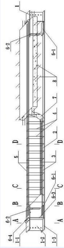
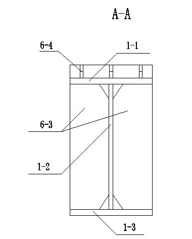
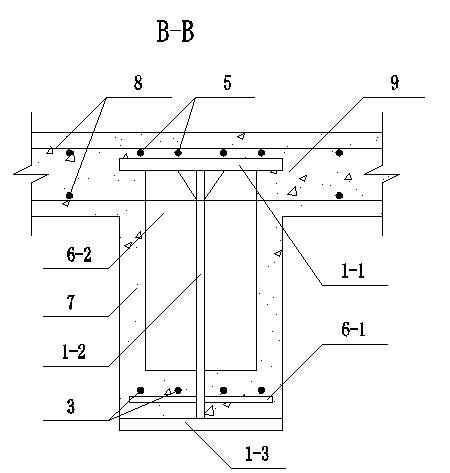
[0008] Specific implementation mode one: combine Figure 1-Figure 8 To illustrate this embodiment, a cast-in-place steel-concrete composite beam of this embodiment includes two I-shaped steel beam sections 1, steel plates 2 in the tension zone, multiple fire-resistant longitudinal reinforcements 3, multiple stirrups 4, multiple Longitudinal reinforcement 5 in compression zone, four longitudinal steel plate stiffeners 6-1, four transverse short steel plate stiffeners 6-2, four transverse long steel plate stiffeners 6-3 and concrete 7, each I-shaped steel beam section 1 The longitudinal length of the upper flange 1-1 is less than the longitudinal length of the lower flange 1-3, and the web 1-2 of each I-shaped steel beam section 1 has a right-angled trapezoidal structure, and the two I-shaped steel beams Section 1 is arranged along the longitudinal direction of any I-shaped steel beam section 1, and the oblique waists of the webs 1-2 of two I-shaped steel beam sections 1 are arr...

specific Embodiment approach 2

[0009] Specific implementation mode two: combination figure 1 To illustrate this embodiment, the I-shaped steel beam section 1 of this embodiment is made of Q235 steel, Q345 steel, Q390 steel or Q420 steel. Other compositions and connections are the same as in the first embodiment.

specific Embodiment approach 3

[0010] Specific implementation mode three: combination figure 1 To describe this embodiment, the steel plate 2 in the tension region of this embodiment is made of Q235 steel, Q345 steel, Q390 steel or Q420 steel. Other compositions and connections are the same as those in Embodiment 1 or Embodiment 2.


PUM


Abstract

The invention discloses a cast-in-place steel-concrete composite beam, which relates to a composite beam. The cast-in-place steel-concrete composite beam solves the problems that a reinforced concrete beam and a column connection node in the existing steel structure and the existing steel-concrete composite structure have complex structures and are difficult to construct, the problems that a common composite beam has a large steel consumption and a high structure manufacturing cost, and the problems that a composite beam of which the publication number is CN101215855 is complex in operation and is inconvenient to construct when connected with a reinforced concrete wall column, and has low bearing capacity, small rigidity, weak spanning capacity, large fracture width for tensile region concrete and small application range. Bottom flanges of two I-shaped steel beam sections of the cast-in-place steel-concrete composite beam and a tensile region steel plate are made into an integral body; a longitudinal steel plate ribbed stiffener is connected through a fire-resisting longitudinal bar; top flanges of the two I-shaped steel beam sections are connected through a tensile region longitudinal bar; stirrups are uniformly arranged along the longitudinal direction of the fire-resisting longitudinal bar; floor steel bars are paved on a stiffening framework of the composite beam; and concrete is poured on the floor steel bars and the stiffening framework of the composite beam. The cast-in-place steel-concrete composite beam is applied to civil engineering constructions.

Description

technical field [0001] The invention relates to a composite beam, which belongs to the technical field of civil engineering. Background technique [0002] Steel structures or steel-concrete composite structures are widely used in multi-storey, high-rise and super high-rise buildings, where frame columns often use steel columns or steel-filled concrete columns or steel-concrete columns, and frame beams use steel-concrete composite beams or reinforced concrete beams . The use of steel-concrete composite beams has the advantages of convenient construction, fast construction speed, high bearing capacity, and strong spanning capacity, but there are also disadvantages such as large steel consumption, need to adopt appropriate fire protection measures, and high structural cost. The use of reinforced concrete beams has the advantages of good fire resistance and low structural cost, but there are disadvantages such as heavy weight and relatively small spanning capacity, especially t...

Claims


Application Information

Patent Timeline
Patent Type & Authority Applications(China)
IPC IPC(8): E04C3/293
Inventor 杨华耿悦赵金涛郭兰慧张素梅
Owner HARBIN INST OF TECH
Why Eureka
Try Eureka