Simulation flame electric fireplace with variable flame color

A technology for simulating flames and electric fireplaces, applied in the field of electric fireplaces, can solve the problems of monotonous flame color, aesthetic fatigue, waste of bulb installation space, etc., achieve the effect of rich flame colors and prevent aesthetic fatigue

Inactive Publication Date: 2017-08-18
NINGBO TEXA ELECTRIC MFG
View PDF6 Cites 0 Cited by
  • Summary
  • Abstract
  • Description
  • Claims
  • Application Information

AI Technical Summary

Problems solved by technology

Through the rotation of the light processing device, the light of the imaging light source is reflected to the imaging screen to achieve the purpose of simulating the dynamic effect of the flame. However, because the structure of the existing light processing device is to install a flexible reflective sheet on the rotating shaft, during the rotation of the rotating shaft The position of the flexible reflective sheet on the shaft is fixed, so the flame pattern presented on the imaging screen changes periodically. The existing imaging device can only adjust the speed of the flame pattern change by adjusting the rotation speed of the shaft. It takes only a short time to rotate a circle, and the user will soon feel tired of the periodic flame changes. At the same time, the existing flame color is relatively single. If you want multi-color flames, you need to install several imaging light sources of different colors in advance. This will waste a lot of light bulbs and the limited installation space in the cabinet is difficult to install many light bulbs. Even if the method of pre-installing imaging light sources of different colors is difficult to meet the actual needs of users due to the limited colors, it is difficult for users to adjust the flame they want. color

Method used


Image

  • Simulation flame electric fireplace with variable flame color
  • Simulation flame electric fireplace with variable flame color
  • Simulation flame electric fireplace with variable flame color

Examples


Embodiment Construction

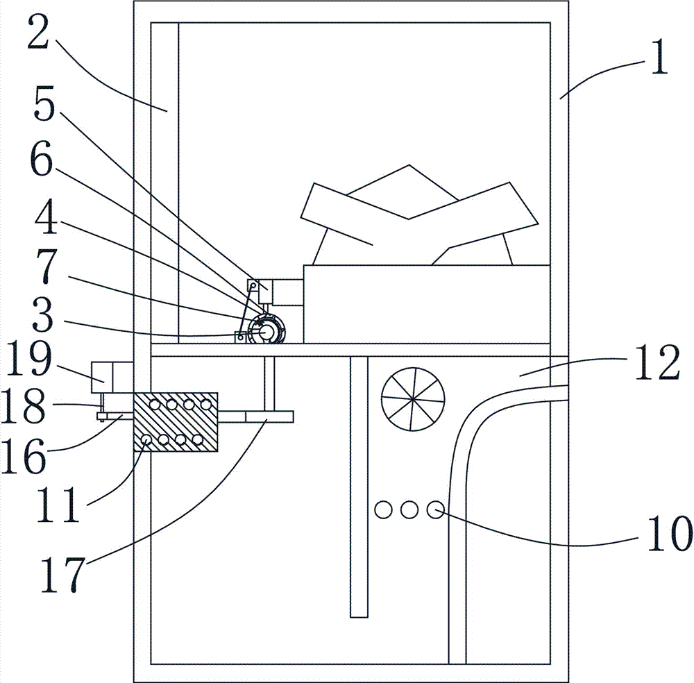
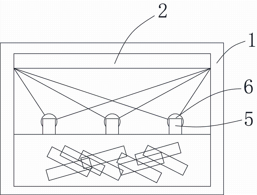
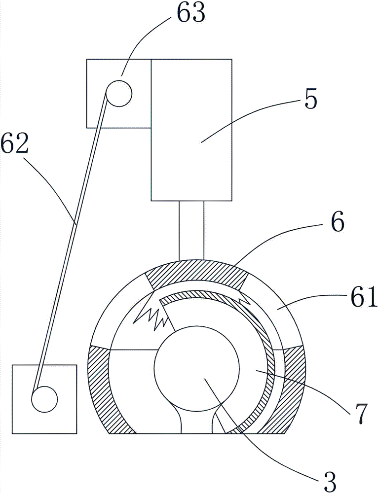
[0013] The present invention will be described in further detail below in conjunction with accompanying drawing and specific embodiment: see Figure 1 to Figure 4 , a simulated flame electric fireplace with variable flame color, comprising a box body 1, an imaging screen 2, an imaging light source 3 and a light processing device 4 are arranged on the box body 1, and three imaging light sources are arranged in the box body 1 3. Each of the imaging light sources 3 is provided with a light processing device 4, and the light processing device 4 includes a rotating motor 5, a rotating sleeve 6 and a reflective sheet 7, and the rotating motor 5 and the rotating sleeve 6, the reflective sheet 7 is arranged between the imaging light source 3 and the rotating sleeve 6, and the rotating sleeve 6 is provided with a flame model light-transmitting portion 61 on the upper circumference, and the reflective sheet 7 reflects the imaging light source 3 and pass through the flame model light-tra...


PUM


Abstract

The invention discloses a simulation flame electric fireplace with a variable flame color. The simulation flame electric fireplace comprises a box. The box is provided with an imaging screen, an imaging light source and a light ray processing device. The light ray processing device comprises rotary motors, a rotary sleeve and a reflector. The reflector is arranged between the imaging light source and the rotary sleeve. The rotary sleeve is provided with flame model light transmitting parts circumferentially. A light filtering strip with a plurality of colors is arranged between each flame model light transmitting part and the imaging screen. The upper end and the lower end of each light filtering strip are both wound on a motor shaft of a winding motor. Control chips are connected to all rotary motors. The electric fireplace can simulate a lifelike flame effect, the flame effect is not repeated periodically as time goes by, meanwhile, the flame color can be adjusted at any time according to the preference, and aesthetic fatigue of people is prevented.

Description

technical field [0001] The invention belongs to the technical field of electric fireplaces, in particular to a simulated flame electric fireplace with variable flame colors. Background technique [0002] With the improvement of people's living standards, electric fireplaces have gradually become household heating equipment for people in winter. Electric fireplaces generally generate heat through the internal heating elements and then release the heat from the electric fireplace box to the room through the fan blades. In order to make the electric fireplace have a flame effect like a real fireplace when in use, the existing electric fireplace is generally equipped with a flame simulation device. , the existing flame simulation device generally includes an imaging light source, a light processing device and an imaging screen. Through the rotation of the light processing device, the light of the imaging light source is reflected to the imaging screen to achieve the purpose of ...

Claims


Application Information

Patent Timeline
IPC IPC(8): F24D13/02F24D19/08F21S10/04F21V13/08F21V14/08
CPCF21S10/046F21V13/08F21V14/08F24D13/02F24D19/08
Inventor 陈灵波
Owner NINGBO TEXA ELECTRIC MFG
Why Eureka
Try Eureka