
Ice breaking machine

A technology of ice crushing machine and motor, which is applied in the fields of ice making, ice storage/distribution, lighting and heating equipment, etc. It can solve the problems of low stability, high cost of use, and small volume of ice crushing machine, so as to improve food safety The effect of improving the uniformity and simple structure

Inactive Publication Date: 2017-08-18
QUAZHOU GANGSHENGLILAI IMPORT & EXPORT TRADE CO LTD
View PDF8 Cites 0 Cited by
  • Summary
  • Abstract
  • Description
  • Claims
  • Application Information

AI Technical Summary

Problems solved by technology

[0002] The use of ice crushers is becoming more and more widespread. The volume of ice crushers in traditional technology is small and the setting of the built-in reamer is relatively low. It is difficult to meet a large amount of ice crushing work. The ice crushing effect is poor, the noise is loud, and the stability is not stable. High, there are many automatic ice crushers with good ice crushing effect and high stability in the existing market, but their cost is high and the operation is complicated. The probability of pollution increases, it is difficult to ensure food safety, there are major disadvantages, and it cannot meet the existing needs

Method used


Image

  • Ice breaking machine
  • Ice breaking machine
  • Ice breaking machine

Examples


Embodiment Construction

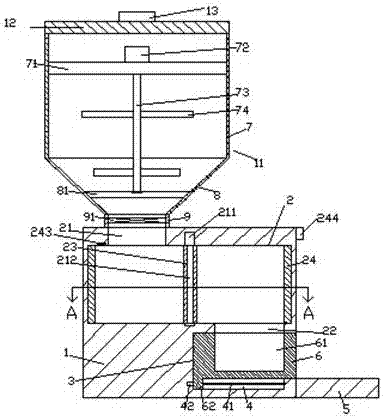
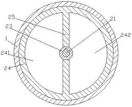
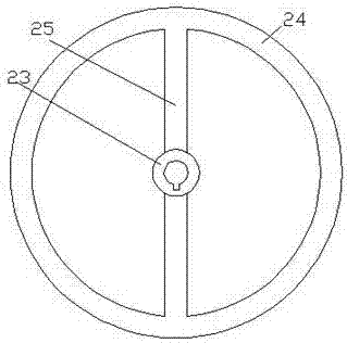
[0021] Such as Figure 1-Figure 6 As shown, an ice crusher of the present invention includes a base body 1 and a bucket box 11 arranged above the base body 1, the top of the bucket box 11 is covered with an end cover 12, and the top of the end cover 12 is A pull ring 13 is provided, and the bucket box 11 includes a first bucket 7, a second bucket 8 arranged at the bottom of the first bucket 7, and a bottom of the second bucket 8. The third bucket 9, the seat 1 is provided with a first cavity 2, and the left top of the first cavity 2 is provided with a first port 21 communicating with the third bucket 9, so The bottom of the right side of the first cavity 2 is provided with a second port 22, the seat 1 at the bottom of the second port 22 is provided with a second cavity 3, and the seat at the bottom of the second cavity 3 The body 1 is provided with a sliding groove 4, and the inside of the first cavity 2 is provided with a sleeve 24 that is rotationally fitted and connected, ...


PUM


Abstract

The invention discloses an ice breaking machine. The ice breaking machine comprises a seat body and a bucket box arranged above the seat body. An end cover is arranged on the top of the bucket box in a covering manner. A pull ring is arranged on the top of the end cover. The bucket box comprises a first bucket-shaped part, a second bucket-shaped part arranged at the bottom of the first bucket-shaped part, and a third bucket-shaped part arranged at the bottom of the second bucket-shaped part. A first cavity is formed in the seat body, a first end opening communicating with the third bucket-shaped part is formed in the top of the left side of the first cavity, and a second end opening is formed in the bottom of the right side of the first cavity. A second cavity is formed in the position, in the seat body, at the bottom of the second end opening. A sliding groove is formed in the position, in the seat body, at the bottom of the second cavity. A cylinder sleeve connected with the first cavity in a swirl fit manner is arranged in the first cavity. A rotating pin shaft is arranged at the position of the middle end of the interior of the sleeve. The outer surface of the rotating pin shaft is sleeved with a rotating cylinder. Partition blocks are correspondingly arranged at the front portion and the rear portion of the rotating cylinder and divide the interior of the cylinder sleeve into a first hollow groove and a second hollow groove. The top of the rotating pin shaft is connected with a first motor, and a container is arranged in the second cavity. The ice breaking machine is simple in structure and convenient to operate, mincing can be automatically controlled, automatic sending-out can be achieved, mincing is relatively even, cleanliness and sanitation in the ice cube mincing process can be ensured, and the edible safety is improved.

Description

technical field [0001] The invention relates to the technical field of ice crushers, in particular to an ice crusher. Background technique [0002] The use of ice crushers is becoming more and more widespread. The volume of ice crushers in traditional technology is small and the setting of the built-in reamer is relatively low. It is difficult to meet a large amount of ice crushing work. The ice crushing effect is poor, the noise is loud, and the stability is not stable. High, there are many automatic ice crushers with good ice crushing effect and high stability in the existing market, but their cost is high and the operation is complicated. The probability of pollution increases, it is difficult to ensure food safety, there are major disadvantages, and the existing demand cannot be met. Contents of the invention [0003] The technical problem to be solved by the present invention is to provide an ice crusher, which can solve the above-mentioned problems in the prior art....

Claims


Application Information

Patent Timeline
Patent Type & Authority Applications(China)
IPC IPC(8): F25C5/04
CPCF25C5/046
Inventor 张雨晴
Owner QUAZHOU GANGSHENGLILAI IMPORT & EXPORT TRADE CO LTD
Learn More